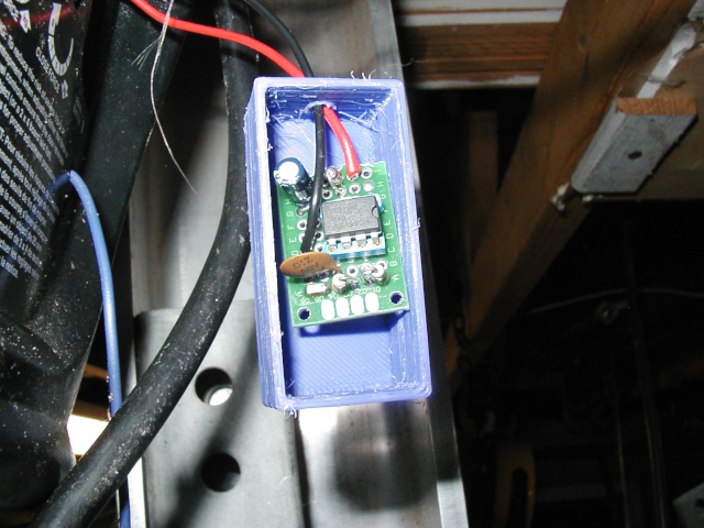
The PCB was mounted in a small 3D printed box with about 4 to 6" of connecting wire that runs to the 2 terminals on the opener motor box.

Garage Door Photocell Bypass Tester

This circuit is used to simulate the photocell pair used across the door opening
of many garage door openers sold since 1993. The design of the drive unit
does not allow the door to operate normally if the photocells are blocked or broken.
The photocells can not be simulated with a jumper wire or open circuit... the
drive must see a pulsed signal to indicate proper operation of the photocells.
The device described on this page provides a valid pulsed signal. It is a 2 wire device constructed on a
small piece of perf board and connects to the main motor housing in place of the photocell
pairs. This is very useful in trouble shooting the door opener operation.
If the door opener does not see the pulsed signal generated by the photocells
(or by this test device), it will open properly, but when you try and close the door,
the door will reverse as soon as you release the button. This is supposed to prevent
you from closing the door on an object that may be blocking the photocell beam.
When this circuit is installed, it simulates the photocell signal indicating that the
beam is clear. The photocells are usually located about 8" off the floor attached
to the door track rail on each side of the door opening. They are prone to damage
and being knocked out of alignment.
The PCB was mounted in a small 3D printed box with about 4 to 6" of connecting
wire that runs to the 2 terminals on the opener motor box.
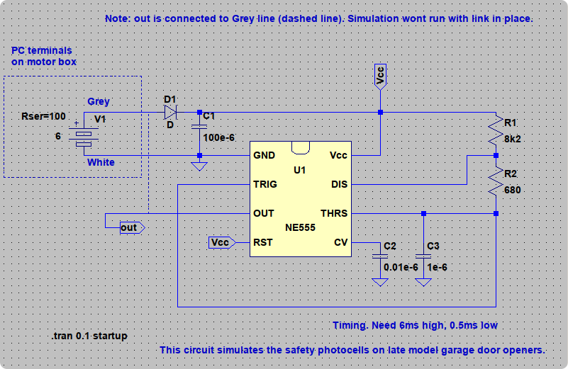
The circuit is a very simple 555 timer chip that generates 0.5ms low pulses
about every 6.5ms. The interface is somewhat novel in that the pulse
signals share the wire with the supply voltage. The door opener circuit supplies about
6.2V with an internal resistance of several hundred ohms to the photocells.
This provides power for the sending unit and the receiving unit as well as a signal
path for the photocell clear state low going pulses. D1 and C1 keep the voltage on the 555
circuit at a little over 5 volts.
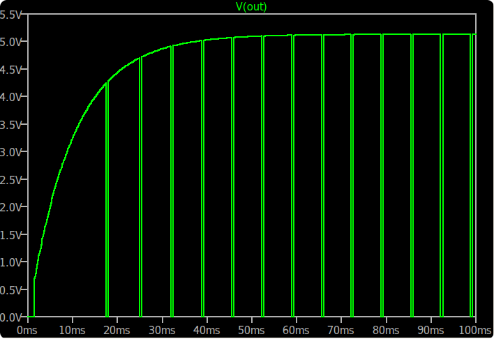
The photocell simulator generates pulses as shown above in the LTSPICE
waveform plot.