Although I have been a ham for many years, I have never considered operating on the 50-54Mhz band (6 meters).
Some local interest in 6 meters started up when the emergency group was looking for a frequency to connect
2 sites that are just out of VHF range and did not have equipment or space for HF antennas. In order to test the link
for an ARDOP data link, several antennas were built and several surplus Kenwood and Motorola Maxtrac radios were modified for
6 meters. This antenna was one of the experimental antennas built to test the suitablity of 6M for the data link.
This antenna was built from scrap aluminum parts.
Tuning turned out to be a multi-day (week?) project.
Intially I tried a coil wound on the lower piece of 1" PVC pipe and could not get anything
close to working. It was determined the coil was just too big.
Next I tried a coil wound on a 1/2" diameter form. This came close to working
when I used the tap at 2.5 turns from ground and the antenna at 5.5 turns from ground.
Tap location and coil size was very critical and confusing. Finally, I decided to measure the raw
antenna impedance using my VNA (another project on this site) and I ran a wire from the vertical to the so-239
feedpoint and measured the raw impedances with the vertical 155" long from tip to feedpoint
and 4 50" radials..
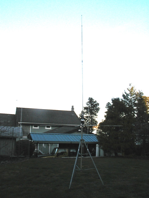
The antenna was mounted with the radials about 6' off the ground on a tripod and
short mast. The vector antenna analyzer was connected to the feedpoint through about 1'
of coax and was calibrated to measure the impedance at the antenna feedpoint.
| Raw Vertical Mesurements |
| Mhz | Impedance |
| 50 | 16.9 -j60.9 |
| 51 | 16.4 -j50.5 |
| 52 | 16.7 -j39.7 |
| 53 | 17.7 -j29.3 |
| 54 | 18.7 -j18.1 |
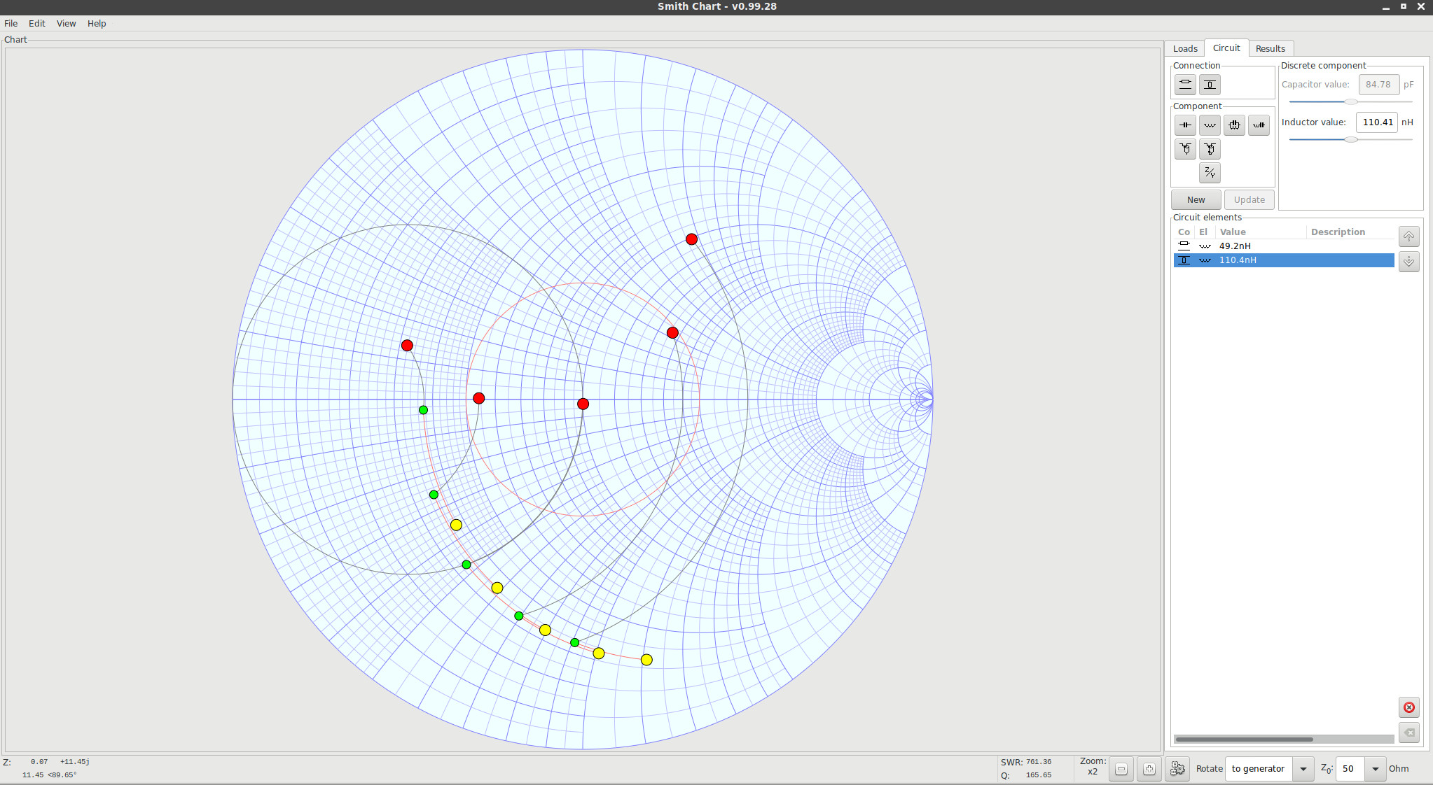
Raw and Matched Solution in Linsmith
Plotting these in linsmith, I played with the coil inductances and determined
that something like 49nH for the top coil and 110nH for the bottom coil would
give a reasonable match.
Using an online inductance calculator, the 49nH coil
could be constructed using 3T of #14 wire wound on a 3/8" drill bit spaced to about
5/8" and the lower coil could be built with 6 turns spaced to about 1".
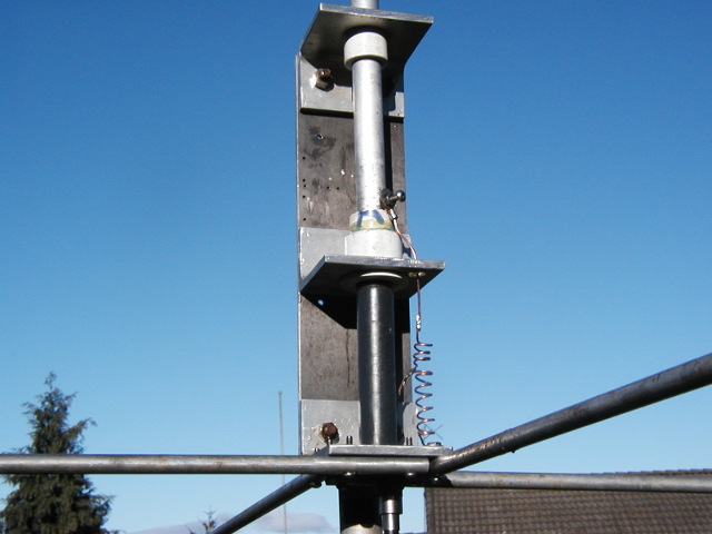
Details: Base of Antenna
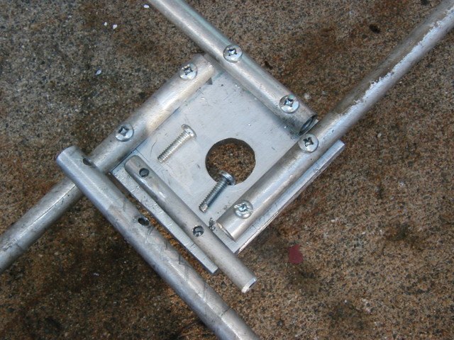
Details: Radial Mounting(note reinforcing tube inside radials)
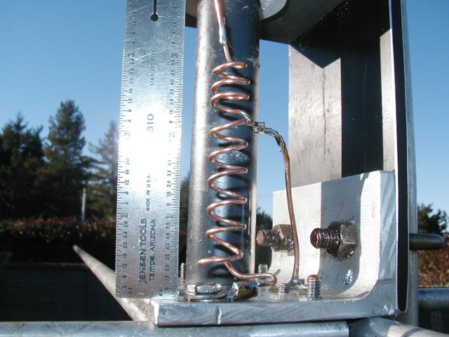
Details: Final Loading Coil Configuration
Using this coil setup, and stretching the coils a bit I was able to get 1:1 SWR at
53.08MHz. To bring it down in frequency I extended the antenna length from
155" up to 160" and had an SWR of 1.02:1 at 51.84MHz.
| Antenna Performance After Matching |
| Mhz | Impedance | SWR |
| 50 | 112.8 +j65.5 | 3.21 |
| 51 | 85.6 +j4.85 | 1.71 |
| 52 | 44.3 +j1.6 | 1.12 |
| 53 | 26.0 +j11.9 | 2.07 |
| 54 | 16.7 +j21.8 | 3.64 |
This parks the antenna just below the FM portion of the band and favors
the low end of the band. Slight length adjustments can move the best match to your favorite
frequency. A 6" change in length moves the antenna about 1.25MHz. Bandwidth is about 2MHz
at the 2:1 SWR points. A scan in the shack shows pretty much that the whole band can be covered while
keeping the SWR inside the 2:1 circle. (ah the joys of feedline loss!)
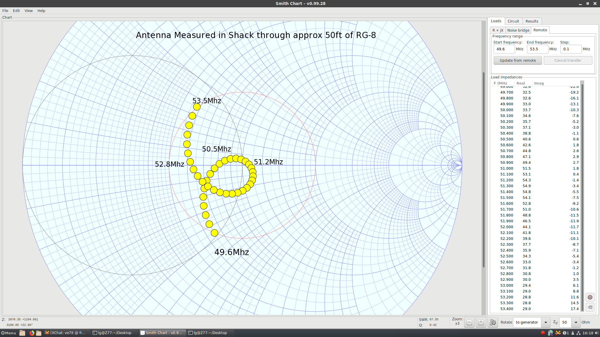
Impedance Measured in the Shack

Supplies and Equipment Needed
- Aluminum tubing for vertical element (old antennas that need to be recycled?) Plan on an overall length of 155 to 165"
- Some smaller approx 3/8" to 1/2" tubing for radials (4 * 50")
- Some aluminum angle for making brackets
- A couple of PVC plumbing fittings for making insulated bushings
- A small plate of aluminum 1/8" to 1/4" thick roughly 3"x12"
- A bit of 14 gauge copper house wire for the coil
- A couple of 2" U bolts (also salvaged off an old triband beam)
- Soldering gun, wire cutter and stripper, some screw drivers, hacksaw, an SWR meter for tuning
Files and Downloads
Load and circuit files for linsmith:
Antenna Raw Load Measurements - 6m-raw.load(524 bytes)
Antenna Matching Solution - 6m-58.cct(647 bytes)
You can download John Coppens ON6JC/LW3HAZ excellent Linsmith program from
linSmith: Smith charting program for Linux
 Back to my Project(s) Page
 6 Meter Five Eigths Wave Vertical Antenna