
Z80 debugging with DSLogicPlus Logic Analyser

This web page is a collection of notes I used when I setup my DSLogic plus logic analyser.
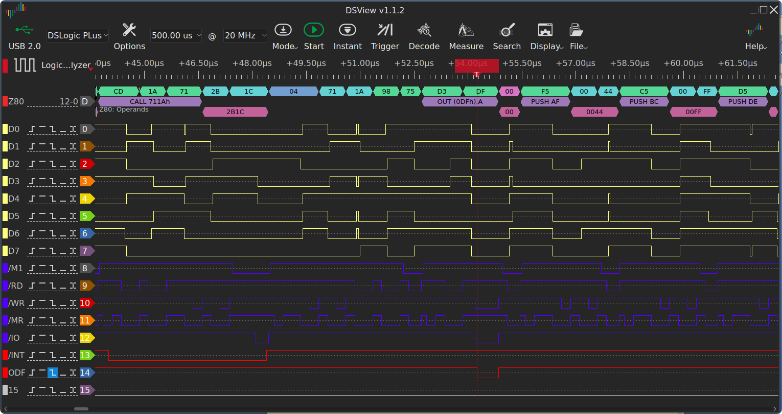
The DSLogic plus is a small hardware USB device used to sample up to 16 logic lines and display
the results on the PC screen in various formats.
The software component is called DSView. My first use of this device was to debug
an interrupt driven serial routine on a S100 Z80 processor board.
When using a logic analyser, there are many ways to connect to your circuit under test.
With 16 signals and 16 ground connections, I didnt really want to use the gripper clips that
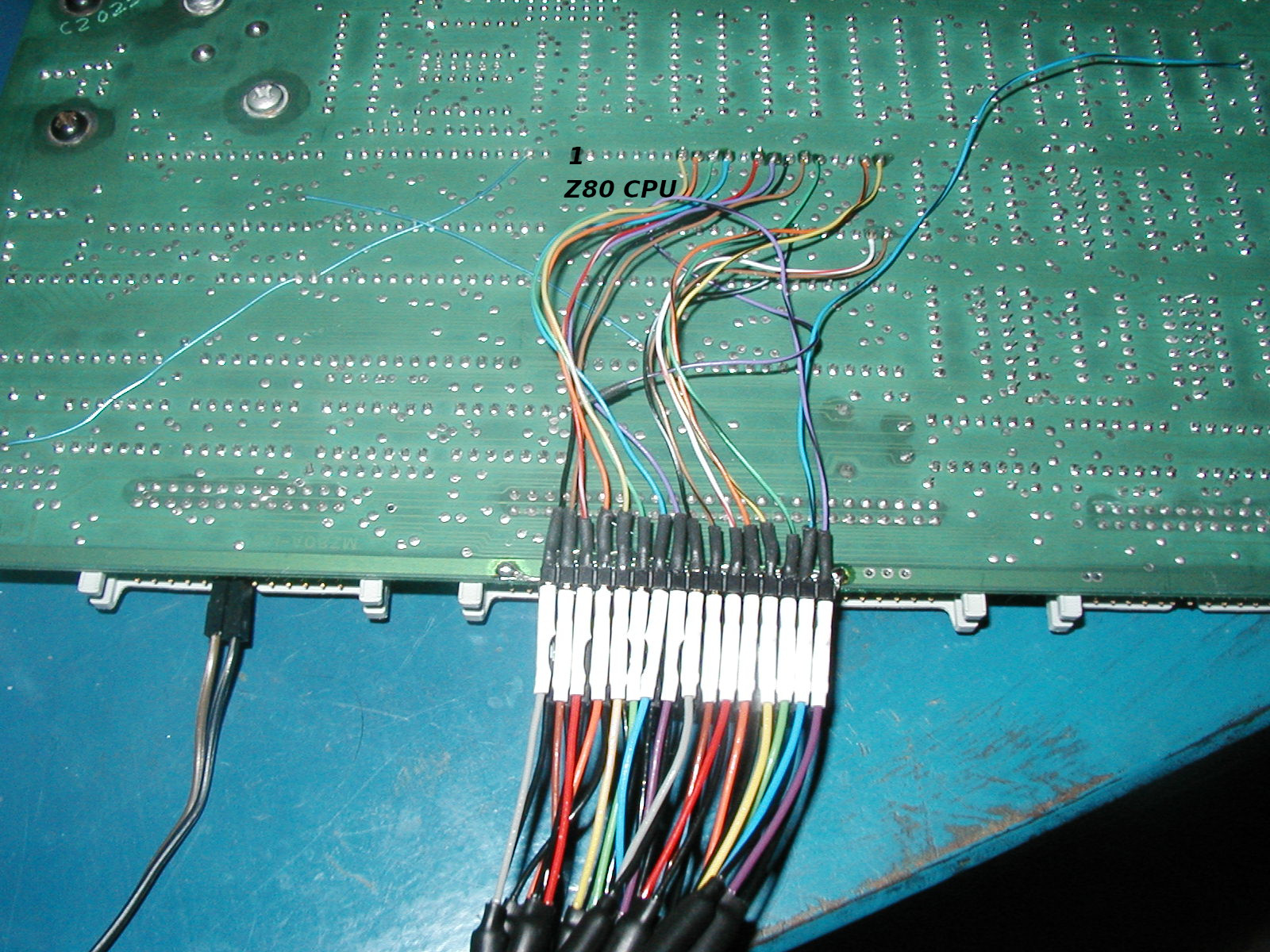
came with the DSLogicPlus. I decided to use pin headers that I hot glued to the back of my test board
and wired the pins into the key z80 signals right on the Z80 socket. This allows me to plug the analyser on
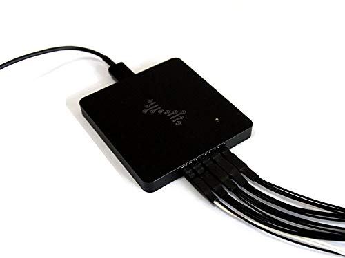
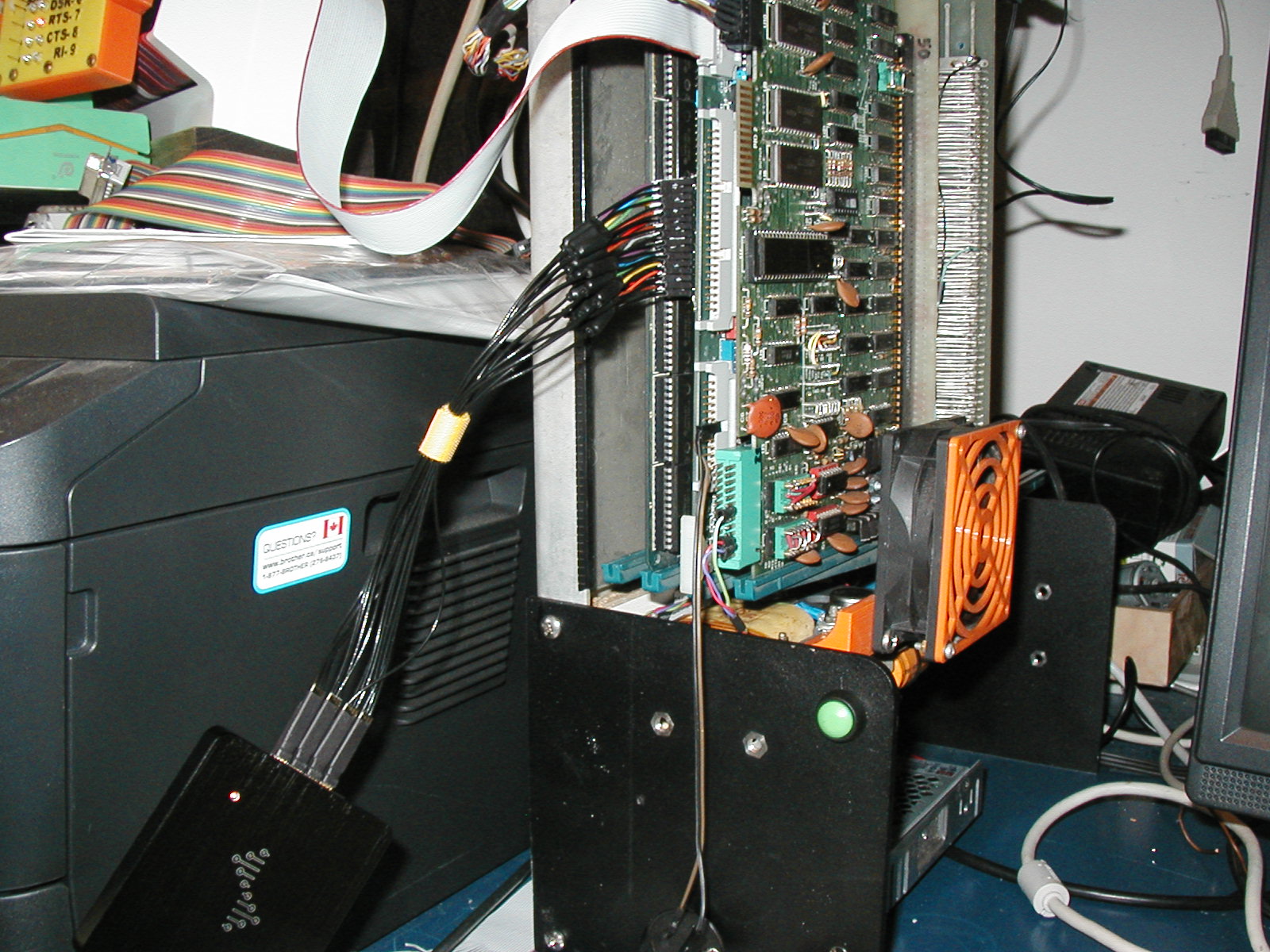
quickly with the board installed in the system bus. The next photo below, shows the DSLogicPlus
connected to my cpu board and the picture below it shows the connections from the pin headers to the
Z80 chip. The blue wire on the right runs off to a spare output port strobe (out 0dfh in my case).
By inserting an out instruction in my code, I can set up to trigger on that point and see
what the code was doing around that area in the program.
Rather than fill this page with details of software setup, I have put all the instructions in a text file dsv-for-z80.txt(6K) that you can print out to follow along when setting up the software. Your situation will probably be different, but the notes will help setting up DSView. The setup is not complicated if you can visualize what you want to watch for. You need to hook the analyser lines up to the hardware under test, tell DSView what each signal line is called, decide how fast and long you want to sample and what you want to trigger on to start the sampling. If you are using one of the built in decoders, you need to configure the decoder to match the signals on the wires.