 Capacitor ESR Tester

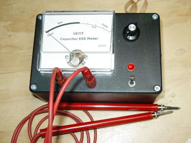
Project Description
This project was conceived as a way to enhance the collection of test equipment on my test bench.
I buy a lot of older HP test gear off ebay as well as older radios. Most of this gear is 25-60 years old
and needless to say, the condition of the electrolytic capacitors is somewhat suspect. I needed a way to
quickly weed out bad caps with an in circuit tester.
At the present time, there are no plans to market circuit boards, kits, parts or complete units
for sale.
What is ESR?
"ESR" stands for equivalent series resistance. ESR is one of the characteristics that defines the performance
of an electrolytic capacitor. Low ESR is highly desirable in a capacitor as any ripple current through the
capacitor causes the capacitor to heat up due to the resistive loses. This heating accelerates
the demise of the capacitor by drying out the electrolyte at an ever increasing rate.
Over the lifetime of a capacitor, it is not uncommon for the ESR to increase by a factor of 10 to 30 times
or even go open circuit. Typical lifetime ratings for electrolytics are 2000-15000 hours and are very dependant on ambient operating temperature. As the ESR increases, the filtering operation of the capacitor becomes impaired
and eventually the circuit fails to operate correctly.
Why are ESR Meters so Useful?
A typical capacitor checker measures the capacity (usually in micro farads) of the test capacitor.
Some advanced units also test for leakage current. Most of these testers require that the capacitor be
removed from the circuit. Unless the capacitor has totally failed, they will not detect a high ESR value.
In a typical circuit, there may be 10's or 100's of capacitors. Having to remove each one for testing is very
tedious and there is a great risk of damaging circuit boards. This tester uses a low voltage ( 250mv )
high frequency (150khz) A/C current to read the ESR of a capacitor in the circuit. The in circuit testing
is possible because of the low voltage used for obtaining the measurement. The voltage is low enough that
solid state devices in the surrounding circuitry are not activated and do not affect the low resistance reading we are attempting to obtain. A lot of capacitor checkers will be damaged if you happen to test a charged capacitor.
This circuit is A/C coupled and will withstand up to 400vdc of charge on a capacitor (but watch your fingers!).
The ESR checker will not detect shorted capacitors as they will read with a very low ESR value. If you are trouble shooting a circuit, you will have to use several instruments including your nose, voltmeter and oscilloscope to locate all the possible failure modes. My experience has found that the ESR meter catches about 95% of capacitor problems and potential problems.
Features
- Tests electrolytic capacitors > 1uf in circuit.
- Caps may be tested in circuit or by bridging them across the terminal posts or using test leads.
- Polarity insensitive testing.
- Tolerates charged capacitors up to 400vdc.
- Low battery draw (approx 25ma) resulting in about 20 hours of battery time when using 4 cheap AA nicads.
- Easy to read analog meter.
- Measures ESR range from 0-75ohms with an expanded scale A/C ohmmeter.
Circuit Description
See the schematic for component designations.
The circuit starts with a 150khz oscillator using one gate of a 74hc14. The rest of the gates are used as
buffers to increase the current drive to the low pass filter. The single pole low pass filter is necessary because the square wave signal contains a lot of energy in high frequency odd order harmonics. The output of the filter is applied across a 10 ohm load resistor that provides the low impedance drive signal to the test capacitor. Diodes D5 and D6 protect the circuit from discharge spikes if you happen to test a charged capacitor. R18 is used to discharge C5 so that you don't blow up anything if you alternately test charged high and low voltage caps. C5 isolates the test circuit from DC voltages up to 400 volts.
Be careful if you are testing high voltage capacitors... the safest way to work is to make sure the test capacitors are discharged before testing them. Be aware that high voltage capacitors can hold a lethal charge for several days depending on the circuit design. I learned this first hand in high school electronics class. Students (not to be named!) used to charge the caps and put them back on the shelf for the next unsuspecting victim to pick up.
The rest of the circuit is a very straight forward transistor amplifier with a gain of about 10.5. This amplifies the
A/C signal passed through the test capacitor up to several volts in amplitude. The signal is then coupled to a full
wave bridge rectifier that has the meter as its load. The threshold voltage of the bridge rectifier is used to an advantage and provides the expanded scale function of the ohm meter. The amplified voltage from the test capacitor must be great enough to overcome 2 diode drops before the meter will start to respond. This sets the high resistance threshold for the meter at somewhere between 75-100 ohms. The meter is zeroed by shorting the test leads together and adjusting the pot in the meter circuit for a full scale ( 0 ohms )reading on the meter. Proper operation of the circuit can be verified by checking several values of resistors with the meter. Shorted leads should indicate full scale, a 1 ohm resistor should read about 90% of full scale, a 10 ohm resistor should read about 40% of full scale and a 47 ohm resistor should barely move the needle to about 10% of FSD. The absolute readings will vary with temperature and battery voltage, but the idea is that most ESR values should be much less than 10 ohms which means good caps test at very close to full scale and bad caps test at little or no deflection.
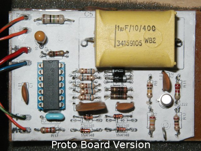
The board below shows my second prototype. The top 2 wires run to the front panel banana test jacks, the middle 2 wires are the incoming switched 5 volts from the 4 AA nicads, and the bottom 2 wires run to the series combination of the zero adjust pot and the meter on the front panel.
Project Files
Schematic Drawing - esrschematic.png(94.7K)
Parts Layout - esrbuildit.png(13.4K)
PCB bottom view - esrpcb.png(4.8K)
PCB Xray View - esrxray.png(4.8K)
Eagle PCB files - esrmeter-9mar05.tgz(173.2K)
LTSpice/SWCadiii - Linear Technology Spice model esr.asc(5.8k)
System Requirements
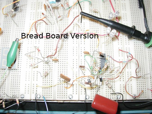
This circuit was first prototyped using a homebuilt prototyping panel. As you can see by the picture above,
it was ugly but it worked. My final version was hand built on a "pad per hole" prototyping board with 0.1" spacing.
I used the PCB layout as a guide for placing and wiring the components (printed and glued to proto board). I did the PCB design as part of the project
so that I could optimize the board size and parts placement. The pcb is roughly 2x3" and is single sided with no
special or critical parts required.
Questions:
John asks:
I have just been looking at you esr tester, I have little experience in electronics
but as part of my college project I have been asked to look into making an esr
tester for 500vdc electrolytic capacitors at 680,000uf. I noticed that your
design is good for 400v, so my question is to you "how might I modify your
design so it works for 500vdc while in circuit" also is there a capacitance
limit to your tester?
Answer:
WOW, you have some mighty impressive capacitors to test!.
The voltage isn't really a problem, as you can just use a higher rated voltage
for C5 (say 1000volts). The problem comes in the capacitance range you wish to
test. The reactance of a 680000uf cap at 150khz is
Xc = 1 / ( 2 * PI * C * F) = 1 / ( 2 * 3.14 * 680000e-6 * 150e3) = 0.00000156 ohm or around 1 micro-ohm.
This is a very difficult measurement as connectors, test leads and contact
resistance will be many orders of magnitude greater than the reactance
you are trying to measure.
As a comparison, testing a 100uf cap, we are looking for reactances of
Xc = 1 / ( 2 * PI * 100e-6 * 150e3 ) = 0.01ohm
This is still hard to do, but when comparing a good 100uf cap with a bad one
(which may have a reactance of 10's of ohms), the simple tester I designed is still functional.
Your capacitor bank sounds like something used in high energy studies like
pulsed laser, rail guns, can crushers or similar. I dont have a simple way
of measuring the ESR of caps in your range.
Updates:
September 2009
The zero of the meter tends to drift with changes in the battery voltage. Several builders have emailed me with modifications to
use a low dropout regulator to keep the voltage more constant. Since my unit runs on 4 nicad cells, there is not enough headroom for a 5volt low dropout
regulator. The charged voltage of my nicad pack is 5.6volts, but most of the packs useful life is down around 4.8volts. I added a
15 ohm 1/2w resistor in series from the battery pack and a 4.7volt 1 watt zener to ground. This modification really helps keep the readings more stable as the
battery discharges. With the lower supply voltage, I had an issue with driving the meter to full scale. I ended up reducing R17 from 10k down to 4k7.
The latest success story using the ESR meter was finding an open 330uF/25v cap on the output of a wall wart supply used with a wireless router. Replacing
the $0.25 part saved me buying a $100.00 router.
March 2017 - Bad motor capacitors.
This unit saved my butt again. I had 2 single phase 3/4HP motors give up the ghost on my table saw and milling machine.
The table saw would not start and the milling machine would start but would not run. On the table saw motor the starting cap was
250uf @ 120VAC and measured over 18 ohms of ESR. The replacement measures only about 0.2 ohms ESR. On the milling machine motor,
there is a start cap and also a run cap. The 300uF cap measured over 23 ohms ESR while its replacement was again only 0.1 to 0.2 ohms ESR.
Both motors are running again after the ESR meter quickly identified the bad capacitors. An autopsy on the duff capacitors revealed
that there was internal corrosion at the connection points and the aluminum foil connections had failed.
 Back to Lawrence's Software Stuff Page