 EU1KY Antenna Analyser( 100KHz-1400MHz )

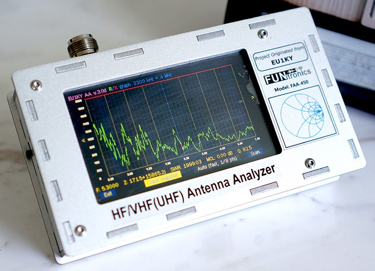
Hardware Package
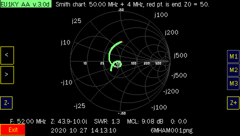
6M vertical scan on smith chart
This page is a description of the customizations I made to the open source/open hardware EU1KY antenna analyzer project.
The FAA-450 Antenna Analyzer is built from a STM32-F7 Discovery board, a small RF board consisting of 2 direct conversion
receivers fed from an RF bridge and a battery/power management board. The analyzer uses DSP techniques to analyze
the 10kHz IF audio output from the direct conversion receivers to compute the complex voltage and current applied to
the antenna port. From this, an OSL (Open/Short/Load) calibration is applied to give a complex impedance value for the antenna.
From this impedance, VSWR may be calculated when referenced to 50ohms (other reference impedances are also supported).
Kits or a built project are available from
www.elekitsorparts.com
This project originated from the EU1KY Antenna Analyzer V3, which features a 4.3" colour TFT LCD,
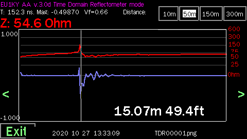
capacitive touch screen, HF/VHF(UHF) frequency coverage, built-in TDR function, signal generator function
and multiple scanning curves for impedance and VSWR measurements. Full open source software is available
via the github link listed at the bottom of this page..
Development is by cross compiling for the STM32F746 board on windows (Embitz IDE) or
linux (makefile with arm-none-eabi-gcc). The generated F7Discovery.bin file is uploaded to the
device using ST-Link loader from
STMicroelectronics.
For windows, you will need to get the STSW-LINK004 utility and STSW-LINK007 windows drivers from the above link.
As of Oct 2020, under arch linux, I have been using the stlink package from the main repository to provide
the st-flash utility for loading either the .bin file or the .hex file of the project (see below for example cmd line).
List of Custom Software Modifications
Notes
Note: if your battery fails to charge, you may need to upgrade the ST-Link firmware on your discovery board. This was discovered when
a stock 32F746GDISCOVERY was used to replace a broken board. Update the ST-Link firmware using STSW-LINK007 package from
https://www.st.com/content/st_com/en/products/development-tools/software-development-tools/stm32-software-development-tools/stm32-programmers/stsw-link007.html#overview.
The update supports windows and linux.
Note: When using a stock board, you need to change 4 jumper settings.
The jumpers on the stock board that need changing: move SB3/SB5 to SB1/SB4. Check SB1/SB4 for continuity and that
SBSB3/SB5 are now open circuit. These jumpers are near the SD card connector and are used to drive the Si5351 SCL/SCD on the RF board.
Note: To program the new image under linux (install stlink package from your os repository):
Connect a mini usb cable to the left most (ST-LINK) port (also used for charging and ttyACM0 serial port for remote control).
"st-flash --format ihex write F7Discovery.hex" or
"st-flash write F7Discovery.bin 0x8000000"
The right most USB port labeled USB-HS is used to access the SD card when the "USBHSReader" main menu option has been selected.
Note: Tips on setting battery voltage monitor. I have not found any mention of how to use the "Config/Accu Settings" screen.
First off, I assume the Accu stands for accumulator ( an alternate name for battery ).
Step 1; set MaxV to 4.200 and MinV to 3.000 by
clicking on the VoltMaxDisplay button and then using the + and - increment/decrement keys to adjust the voltage. These numbers make
sense if you are using a standard 18650 LiPo cell as a power supply. The high number is used to indicate the full charged voltage
where the battery capacity is defined at 100%. The lower number defines the voltage when the battery is basically considered flat
with 0% capacity.
Step 2; charge the unit until the battery is fully charged ( charge LED on power board goes out ).
Step 3; once the battery
is fully charged go back to the "Config/Accu Settings" screen and check it remembered you MaxV and MinV settings, press the "Set Max Value"
button. This sets the A/D scaling for the battery measurement circuit. It is assumed that when you press this button that the battery is fully charged
and is at the MaxV value. You will see MaxFact field update which I believe is the A/D counts/volt scaling factor. The battery display should now
be reasonably useful to indicate how close you are getting to battery charge depletion.
Note: The connections to the STM audio inputs on the blue 3.5mm connector appear to be critical to proper operation.
If you do the hardware calibration and then the OSL calibration and do a wide band SWR scan of the load, you should see
an SWR line very close to one. This is really the definition of calibration. If you see a very ragged
line with SWR reading bouncing around from 2 to 20, you may have to try swapping the 2 audio signals at the blue mic jack on the
STM discovery cpu board. Also before calibration you should check that the configuration has been set up for the
SI5351_MAX_FREQ (260Mhz for mine), OSL_RLOAD (50), OSL_RSHORT (0), OSL_ROPEN (Open), BAND_FMIN (100kHz), BAND_FMAX (1300MHz).
Any changes to the above configuration items must be followed by a new HW calibration as well as the 3 part OSL (open,short,load)
calibration.
Note: I had an issue compiling the project under embitz. Some how, some of the code got compiled with hardware floating point support and
some of it without. Everything compiled, but I got a whole lot of ld (link) errors at the end of the build process. To repair this,
in embitz, goto build/clean workspace. I had been using build/clean target which did not solve the issue.
Files / Downloads / Links
Free windows IDE for ARM(also runs under linux wine): https://www.embitz.org/.
STMicroelectronics ST-Link software: https://www.st.com/en/development-tools/st-link-v2.html.
My Github Page: https://github.com/ve7it/Analyzer_EU1KY_CEC_AKF
You can download John Coppens ON6JC/LW3HAZ excellent Linsmith program from
https://sourceforge.net/projects/linsmith/
My linsmith remote control patch: linsmith-remote.patch for linsmith-0.99.28 (19.2kB).
My 6M 50MHz antenna being measured above: http://ve7it.cowlug.org/6m-five-eigths.html .
Analyzer kit/assembled supplier: www.elekitsorparts.com
 Back to my Project(s) Page