Project Description
This web page is a journey through my efforts to build a low cost hex beam antenna for
the 5 ham bands from 14 to 28 MHz. This construction project involved some scrounging, welding,
3D printing, 4nec2 simulations, some ebay purchases, and a lot of sifting through the junk box.
It does not have step by step instructions, but provides information and ideas that one can use to create
a working hexbeam antenna. The performance of this antenna design has been outstanding. It does not seem to need large
antenna towers and in my design I aimed for getting the 20M element about 1/2 wavelength off the ground.
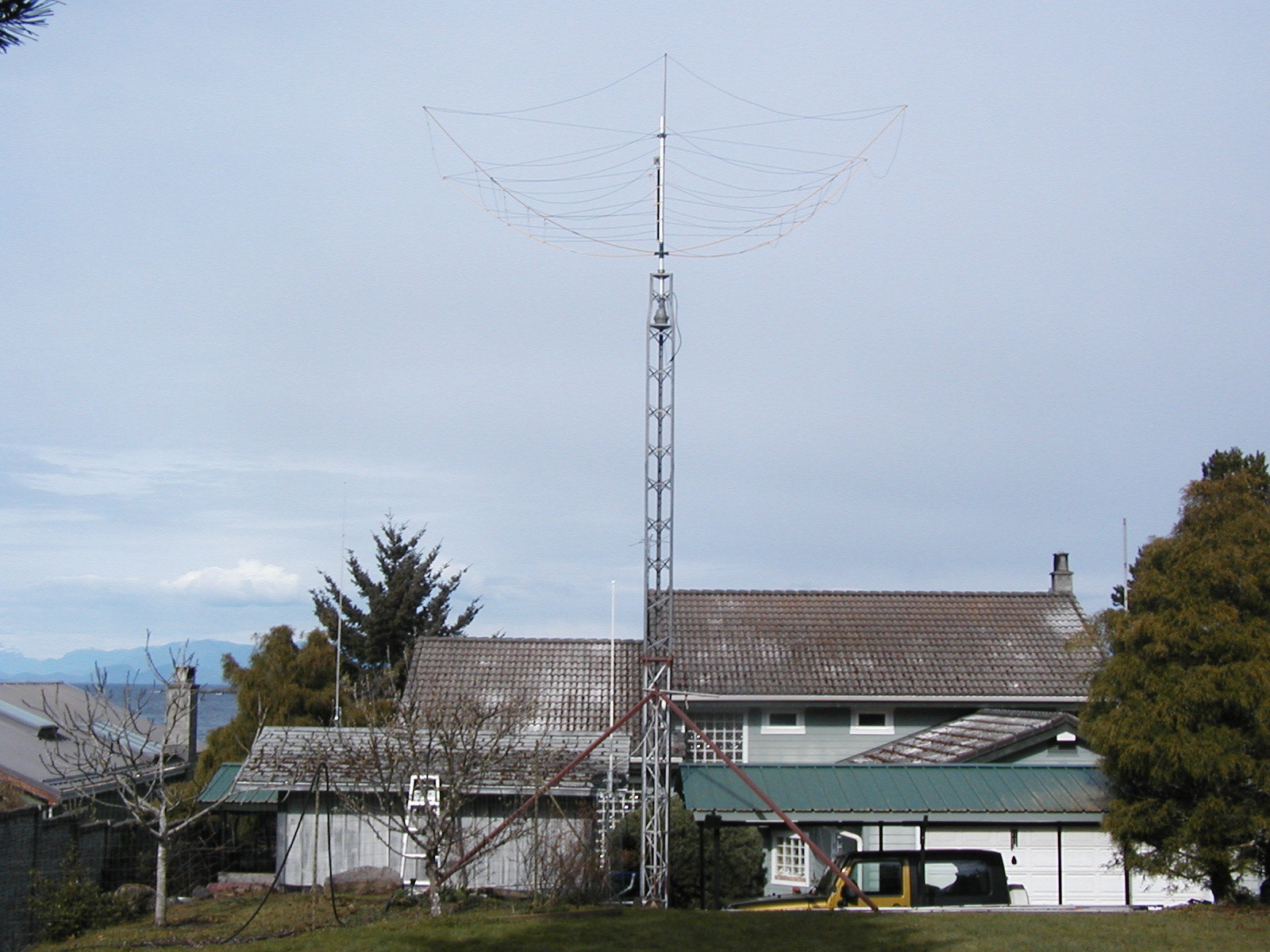
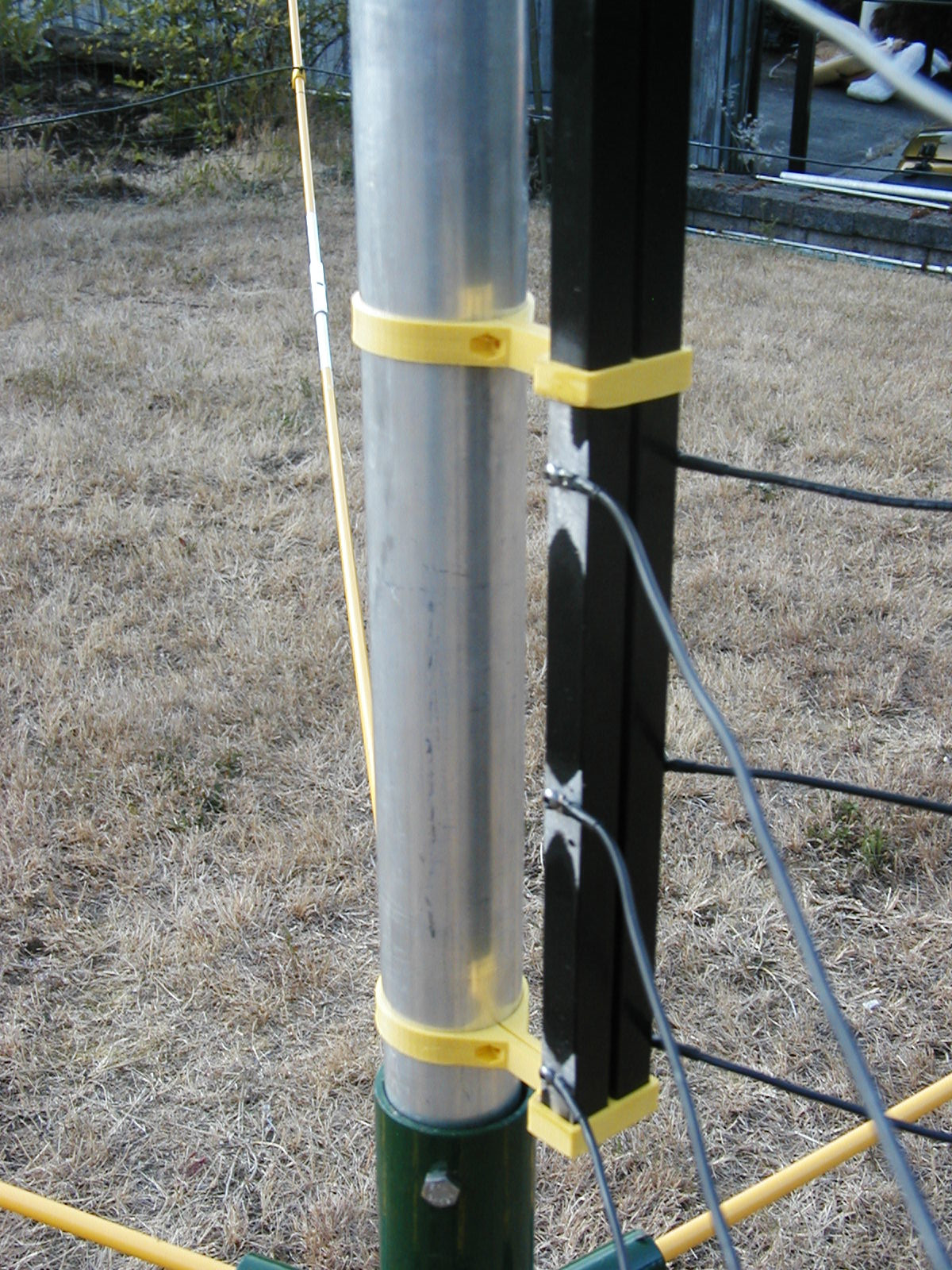
The antenna started with a central mast section consisting of a 2" aluminum pipe
8 feet long. This was a heavy wall mast obtained from our local hardware/surplus store
(Princess Auto) for around $40.
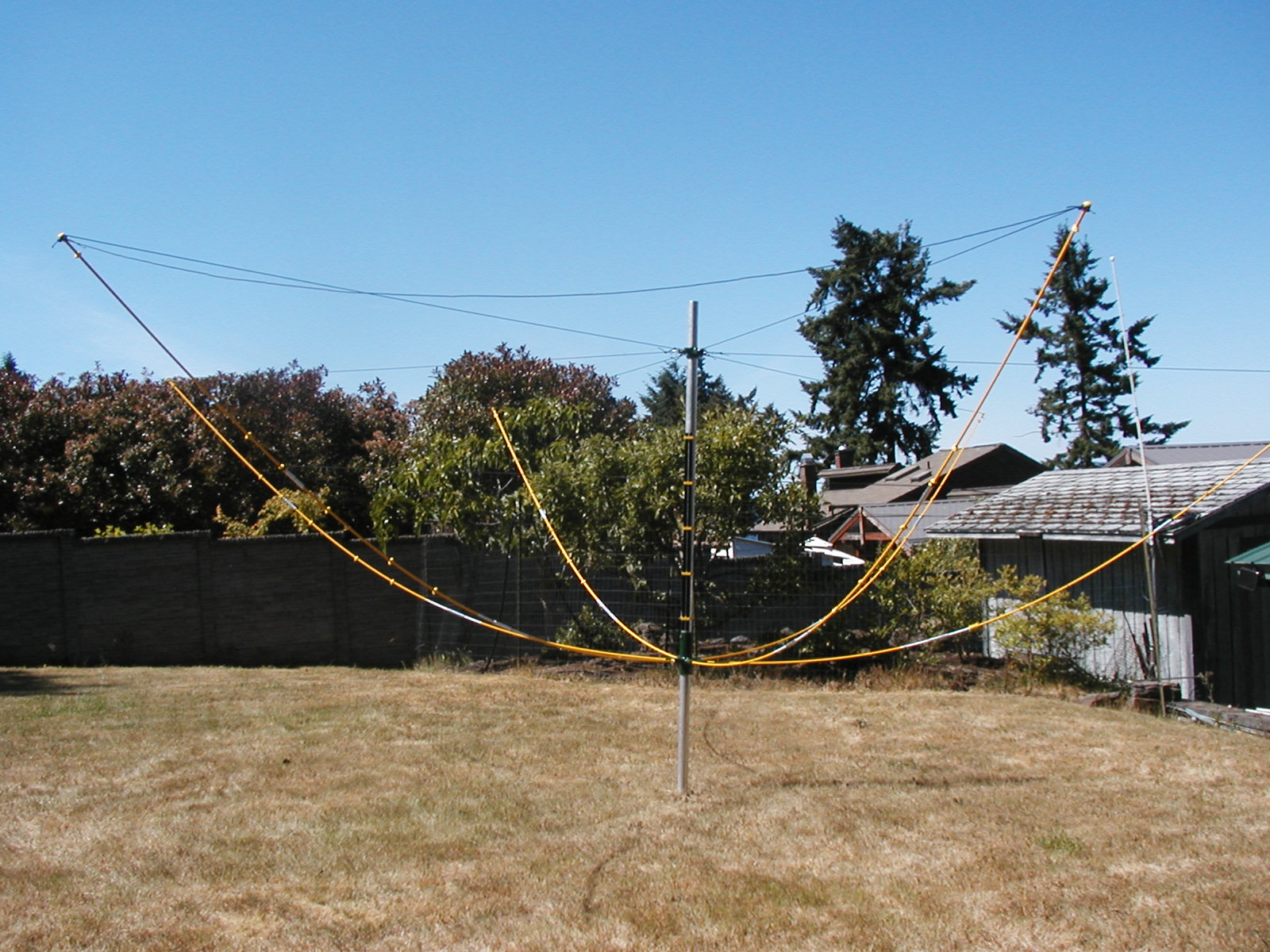 The above picture shows the antenna sitting on the lawn (positioned over a piece of rebar
pounded into the grass). Most of the assembly was done at this level without the need for ladders.
The above picture shows the antenna sitting on the lawn (positioned over a piece of rebar
pounded into the grass). Most of the assembly was done at this level without the need for ladders.
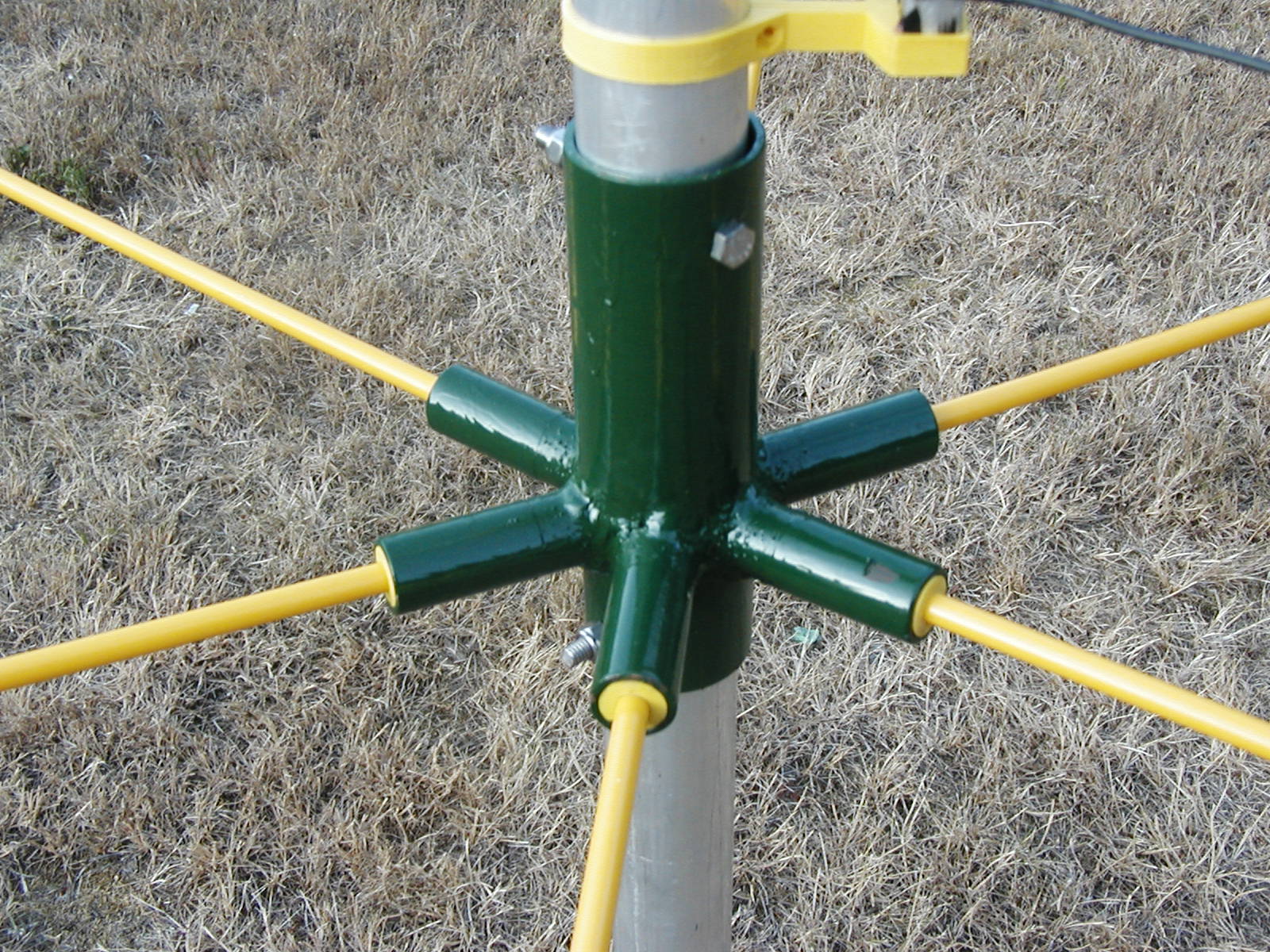
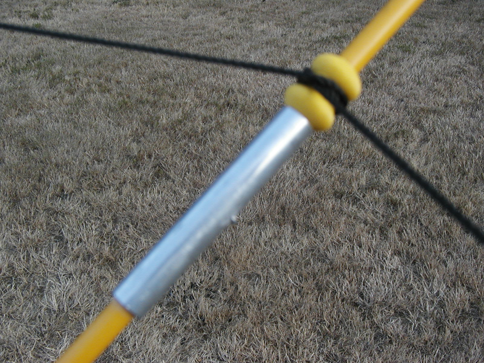
The hub that supports the spreaders was welded up from several pieces of scrap galvanized water pipe.
This was placed over the mast section and bolted in place leaving enough of the mast below the
hub to allow the mast to protrude through the thrust bearing on the top of the tower and be
clamped into the rotor assembly. You can see in the picture below that the spreaders were
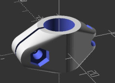
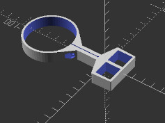
adapted to fit into the 6 smaller pipes by using 3D printed sleeves (printed in PETG).
The spreaders are a snug friction fit in the plastic sleeves and may be removed for replacement
or moving/storing the antenna.
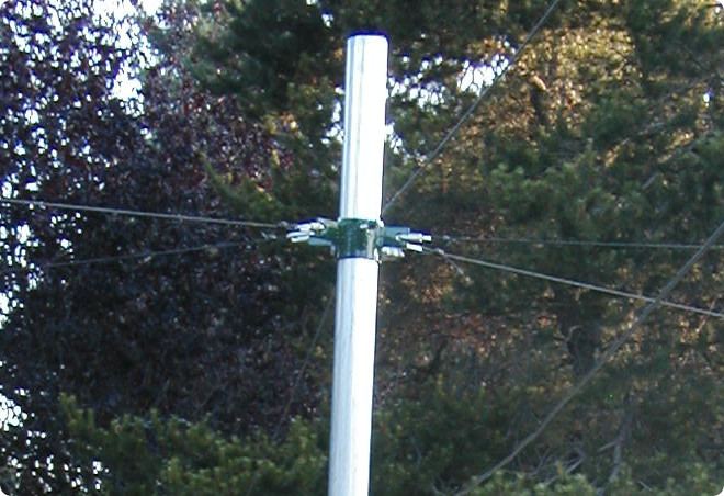
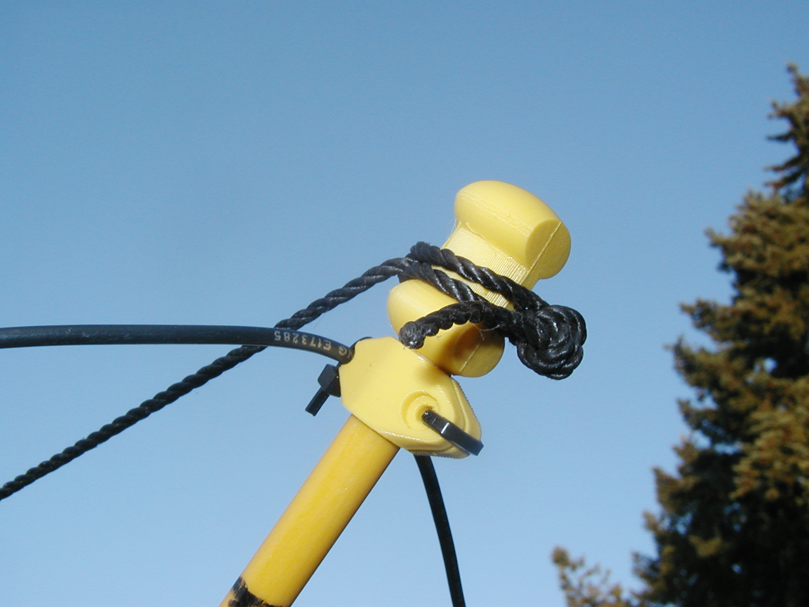
The second welded bracket is used to secure the spreader tension ropes near to top of the mast.
This was built from some of the same pipe used in the lower bracket with 6 flatbar tabs welded
around the perimeter. Stainless steel chain quick links were used to transition from holes in the flatbar to the
UV resistant cord used for the spreader tension components. The assembly was bolted through the mast
slightly below the top of the mast. My idea was to mount a small directional VHF/UHF antenna on top at a later date.
The spreaders were one of the hardest components to locate for the build. One needs 6 poles around 12 feet long.
It is possible to buy replacement spreaders from some of the hexbeam manufactures,
but a set of commercial spreaders run into the hundreds of dollars. I looked at using fishing rod blanks,
PVC pipe, chimney cleaning rods and other sources of fibreglass tubing or rods.
 By far, the cheapest solution was 4' long fibreglass rods ($3 each or 2$ each if you catch them on sale!) used for marking driveway edges
(thanks again to Princess Auto). The heavy duty rods are 10mm diameter and are joined by short sections of
aluminum tubing found on ebay. The tubing is 10mm ID and 14mm OD and came in 1 foot lengths. I needed 12 joiners
so I cut each piece of pipe into roughly 4" lengths. I cross drilled each joiner and put a short piece
of aluminum welding wire through the center of each joiner. This acts as a stop for inserting each of the fibreglass
rods and holds the joiner in position on the assembled spreader. I thought of glueing these connections,
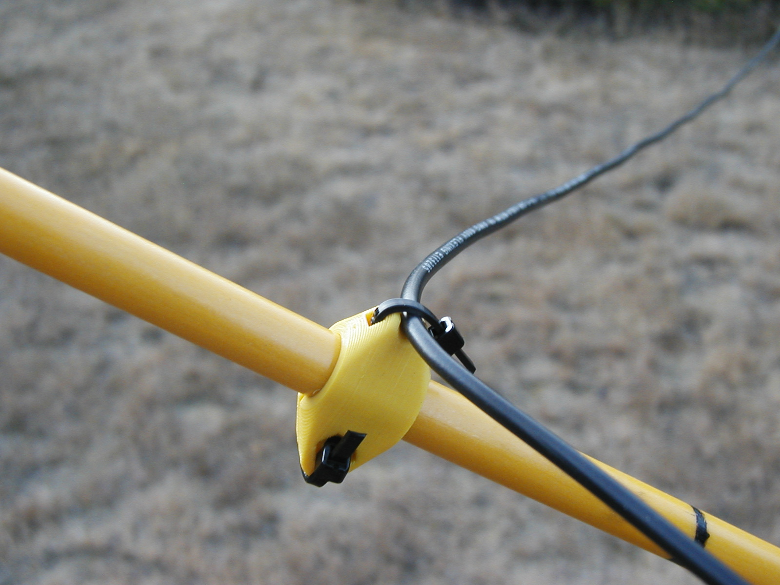
but for now they are just a friction fit which allows easy disassembly. The above picture also
shows another 3D printed part that I used to secure a stabilizing cord around the perimeter of the antenna just above the
second joint. This perimeter cord a holds the spreaders
in position. I bought the UV resistant cord from a local fishing supply store. It is approximately 1/8"
in diameter and came in a big spool thousands of feet long. It is my go to for hanging wire antennas.
By far, the cheapest solution was 4' long fibreglass rods ($3 each or 2$ each if you catch them on sale!) used for marking driveway edges
(thanks again to Princess Auto). The heavy duty rods are 10mm diameter and are joined by short sections of
aluminum tubing found on ebay. The tubing is 10mm ID and 14mm OD and came in 1 foot lengths. I needed 12 joiners
so I cut each piece of pipe into roughly 4" lengths. I cross drilled each joiner and put a short piece
of aluminum welding wire through the center of each joiner. This acts as a stop for inserting each of the fibreglass
rods and holds the joiner in position on the assembled spreader. I thought of glueing these connections,
but for now they are just a friction fit which allows easy disassembly. The above picture also
shows another 3D printed part that I used to secure a stabilizing cord around the perimeter of the antenna just above the
second joint. This perimeter cord a holds the spreaders
in position. I bought the UV resistant cord from a local fishing supply store. It is approximately 1/8"
in diameter and came in a big spool thousands of feet long. It is my go to for hanging wire antennas.
 The picture above shows the top end of one of the spreaders with details of the cord
securing the spreader tip back to the central mast and the attachment of the 20 meter
element using a small 3D printed part. The wire is stranded 16 gauge insulated hookup wire.
You will need about 275' of wire for 20 through 10 meter elements. I used wire off a 500ft spool
and have plenty left for more antenna projects.
The picture above shows the top end of one of the spreaders with details of the cord
securing the spreader tip back to the central mast and the attachment of the 20 meter
element using a small 3D printed part. The wire is stranded 16 gauge insulated hookup wire.
You will need about 275' of wire for 20 through 10 meter elements. I used wire off a 500ft spool
and have plenty left for more antenna projects.
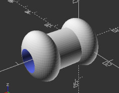
 The 3D printed wire supports were designed to use a nut and bolt to secure them on the spreader rods.
The supports fit snuggly and I just used a wire tie to keep them closed on the rod. It is easy to slide the
the supports up and down the rods to optimize the wire tension. The element wires do not need to be tight
and a little sag is fine.
The 3D printed wire supports were designed to use a nut and bolt to secure them on the spreader rods.
The supports fit snuggly and I just used a wire tie to keep them closed on the rod. It is easy to slide the
the supports up and down the rods to optimize the wire tension. The element wires do not need to be tight
and a little sag is fine.
 One of the key features in feeding a hex beam is the connections between the 5 antennas.
Other hex beam designs I found on the net used the mast as a 50 ohm coaxial transmission line
(lots of fiddly mechanics ) or used short 50 ohm sections of coax to jump between the 5 driven elements
(way too many chances for water contamination). I elected to build a section of 50 ohm parallel transmission line
using some aluminum square tubing (spindles from aluminum hand railing). Using the dimensions of the tubing,
one can find the spacing needed to form a 50 ohm transmission line.
One of the key features in feeding a hex beam is the connections between the 5 antennas.
Other hex beam designs I found on the net used the mast as a 50 ohm coaxial transmission line
(lots of fiddly mechanics ) or used short 50 ohm sections of coax to jump between the 5 driven elements
(way too many chances for water contamination). I elected to build a section of 50 ohm parallel transmission line
using some aluminum square tubing (spindles from aluminum hand railing). Using the dimensions of the tubing,
one can find the spacing needed to form a 50 ohm transmission line.
See https://hamwaves.com/zc.square/en/index.html
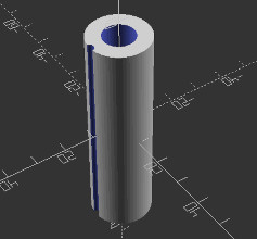
Again thanks to 3D printing, I designed standoffs that space the transmission line away from the mast to
reduce coupling and to hold the 2 aluminum tubes at the correct distance apart to form a 50 ohm transmission line.
The square aluminum tubing was drilled and tapped for attaching each of the 5 driven elements.
Each driven element was terminated with a soldered on ring terminal and the junctions coated with dielectric grease
to give some protection from the weather.
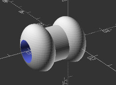
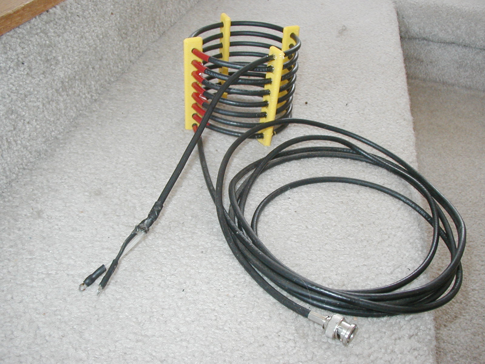 The top of the transmission line was fed with a choke balun consisting of 8 turns of RG-58 coax
supported by 3D printed spacers.
The top of the transmission line was fed with a choke balun consisting of 8 turns of RG-58 coax
supported by 3D printed spacers.
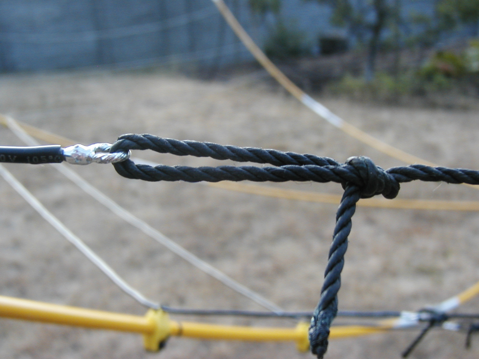 The far ends of each of the driven elements is connected to a short spacer of cord that connects to the reflector
element on each band. I looked at using small fibreglass rods as the insulators but decided simple was better. I formed
an eye at each end of the elements as shown above and used the fishing cord with bowline knots to form the spacer.
It was easy to form the eye around a screwdriver shaft and twist the connection. I quick coating of solder gives the
joint some strength and stops water from wicking up the wire strands. I did add some dielectric grease to help waterproof the
wire end.
The far ends of each of the driven elements is connected to a short spacer of cord that connects to the reflector
element on each band. I looked at using small fibreglass rods as the insulators but decided simple was better. I formed
an eye at each end of the elements as shown above and used the fishing cord with bowline knots to form the spacer.
It was easy to form the eye around a screwdriver shaft and twist the connection. I quick coating of solder gives the
joint some strength and stops water from wicking up the wire strands. I did add some dielectric grease to help waterproof the
wire end.
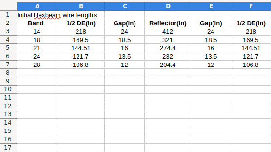 The table above lists the lengths of each of the band elements used for the initial construction.
I built each band element (combination of the driven elements, 2 spacers and the reflector) and mounted it on the
support structures.
The table above lists the lengths of each of the band elements used for the initial construction.
I built each band element (combination of the driven elements, 2 spacers and the reflector) and mounted it on the
support structures.
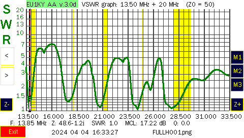 The graph above shows an SWR sweep from 13.5 to 33.5 MHz. The yellow sections show the position and width of
each of the ham bands. As can be seen, each band has the best match just below the ham band. The frequency being low makes it
much easier to shorten the driven elements than to lengthen them. The insulation on the wire
likely caused the several percent error in resonant frequency. If you use bare wire or different gauge wire you will have
to experiment with the lengths as well.
The graph above shows an SWR sweep from 13.5 to 33.5 MHz. The yellow sections show the position and width of
each of the ham bands. As can be seen, each band has the best match just below the ham band. The frequency being low makes it
much easier to shorten the driven elements than to lengthen them. The insulation on the wire
likely caused the several percent error in resonant frequency. If you use bare wire or different gauge wire you will have
to experiment with the lengths as well.
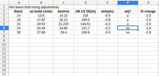 I did a quick spreadsheet shown above and intend to adjust the driven elements by a few inches shown in column E.
This should center the antenna more in the frequency range of my preferred operation. Stand bye for final results!
I dont think I will have to adjust any reflector lengths.
I did a quick spreadsheet shown above and intend to adjust the driven elements by a few inches shown in column E.
This should center the antenna more in the frequency range of my preferred operation. Stand bye for final results!
I dont think I will have to adjust any reflector lengths.
Building The Foldover Tower
 This part of the antenna system started with making a solid base for the tower.
The location selected is centrally located on my lot which happens to be covered with
a concrete driveway. The first job was to punch a hole through the driveway to gain access
to the bedrock which was known to be close to the surface at this location.
I drilled holes with a hammer drill and used a diamond blade on the skill saw to cut
partially through the driveway. Next chore... bring on a chisel and sledge hammer!
This part of the antenna system started with making a solid base for the tower.
The location selected is centrally located on my lot which happens to be covered with
a concrete driveway. The first job was to punch a hole through the driveway to gain access
to the bedrock which was known to be close to the surface at this location.
I drilled holes with a hammer drill and used a diamond blade on the skill saw to cut
partially through the driveway. Next chore... bring on a chisel and sledge hammer!
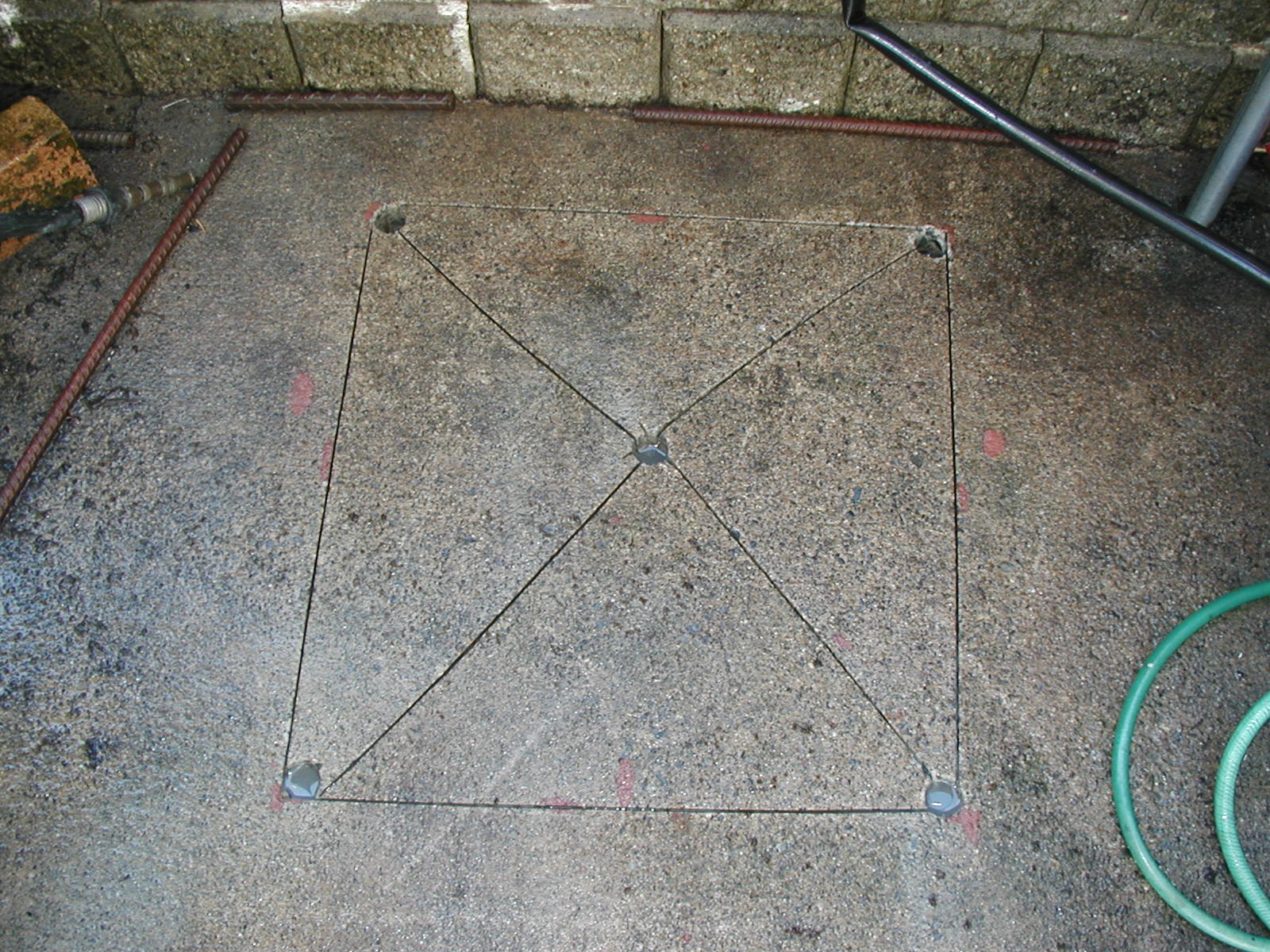
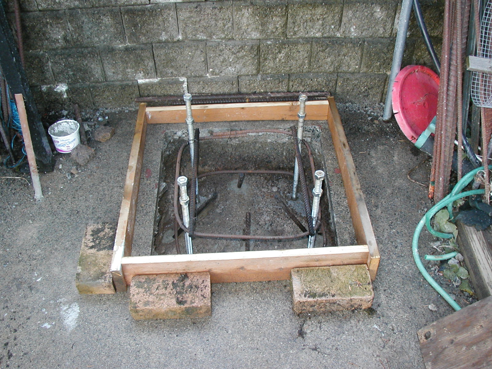 The picture above shows the four 3/4" stainless rods used to bolt to the baseplate.
Also shown is four pieces of rebar grouted into the bedrock at an angle. A collar tie
of rebar was used to reinforce around the 4 base plate bolts. A wooden form was constructed
for the concrete and placed around the hole. The resulting concrete base is about
24"x24" and covers the hole cut in the driveway.
The picture above shows the four 3/4" stainless rods used to bolt to the baseplate.
Also shown is four pieces of rebar grouted into the bedrock at an angle. A collar tie
of rebar was used to reinforce around the 4 base plate bolts. A wooden form was constructed
for the concrete and placed around the hole. The resulting concrete base is about
24"x24" and covers the hole cut in the driveway.
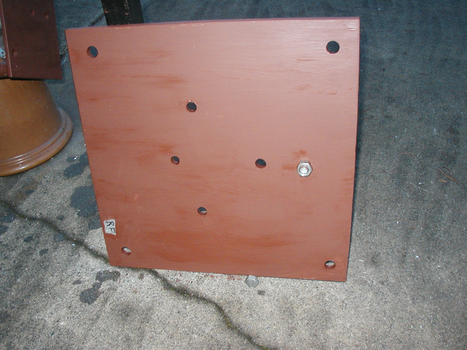 To transition from the four anchor bolts to the plate on the bottom of the
tower section I used a 1/2" plate drilled with 3/4" and 5/8" holes as shown above.
The plate is coated with metal primer to help with keeping corrosion under control
in this seaside location.
To transition from the four anchor bolts to the plate on the bottom of the
tower section I used a 1/2" plate drilled with 3/4" and 5/8" holes as shown above.
The plate is coated with metal primer to help with keeping corrosion under control
in this seaside location.
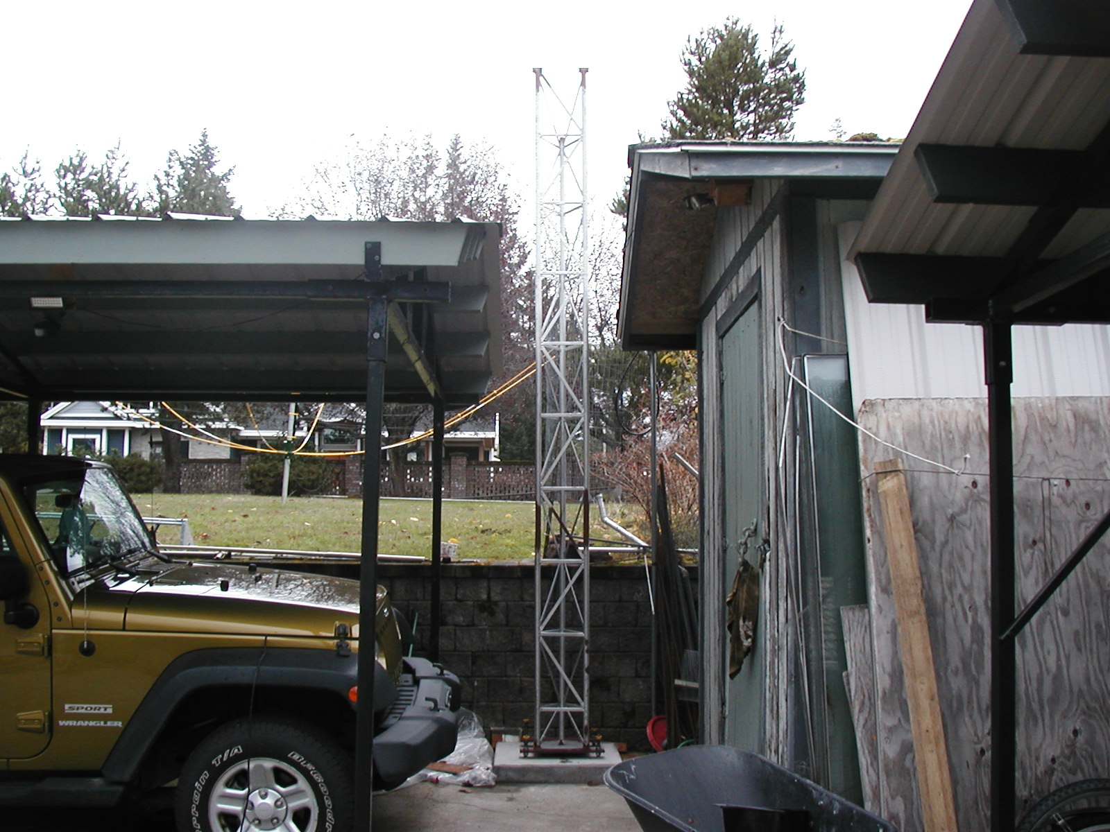 The base plate is bolted to the concrete base and the lower fixed tower section
is bolted to the base plate. The lower tower section is about 12.5' high. I needed
to use a fixed section of tower to raise the hinge point above the retaining wall and to
provide a somewhat centralized balance point for the moving section of tower. Note
that it took some head scratching to get the tower orientation correct so that the
moving section of tower would clear the car port and garden shed.
The base plate is bolted to the concrete base and the lower fixed tower section
is bolted to the base plate. The lower tower section is about 12.5' high. I needed
to use a fixed section of tower to raise the hinge point above the retaining wall and to
provide a somewhat centralized balance point for the moving section of tower. Note
that it took some head scratching to get the tower orientation correct so that the
moving section of tower would clear the car port and garden shed.
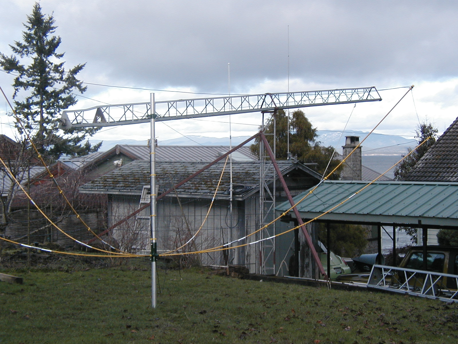 To further support the base section of tower, I added two outrigger legs
that tie the fixed tower section from near the hinge point to a couple of
anchors points poured in the grass area. This resulted in a very rigid
fixed tower section in the form of an asymmetrical tripod.
To further support the base section of tower, I added two outrigger legs
that tie the fixed tower section from near the hinge point to a couple of
anchors points poured in the grass area. This resulted in a very rigid
fixed tower section in the form of an asymmetrical tripod.
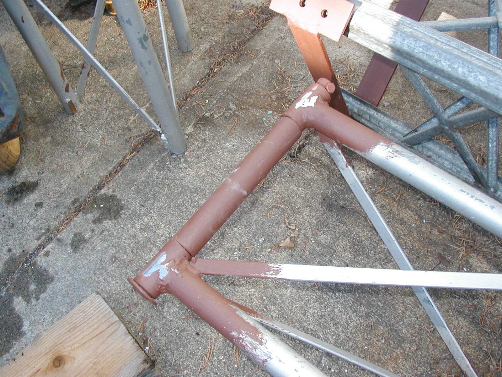 The tower hinge section was constructed from two pipe collars welded to legs of the tower.
The hinge pin was made from 1" mild steel bar stock. The pipe located in the center of the picture
above was welded to a tower bridle which can be seen in the very upper portion of the picture.
The tower hinge section was constructed from two pipe collars welded to legs of the tower.
The hinge pin was made from 1" mild steel bar stock. The pipe located in the center of the picture
above was welded to a tower bridle which can be seen in the very upper portion of the picture.
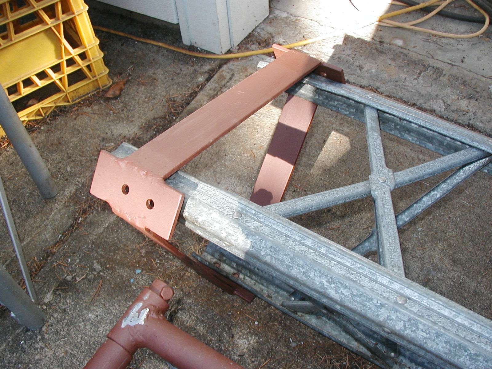 Two of the above bridle assemblies were constructed from 2"x1/4" flat bar.
One of them bolts to the moving section of tower at the hinge point and the other
bolts to the base of the moving section of the tower and is used to secure
the moving tower section to the fixed tower section. These bridle sections
have holes spaced to match the bolt pattern used to connect the moving tower
sections together. To insure a good supportive fit to the tower, the tower sections
were bolted together with the drilled flat bar in place. Then the longer sections of
flatbar were cut to length and tacked in place. The bridle at the hinge point
serves two purposes. It supports the entire weight of the antenna/tower/rotor and it
stops the tower deforming (buckling) due to the forces on the tower during foldover operations.
Two of the above bridle assemblies were constructed from 2"x1/4" flat bar.
One of them bolts to the moving section of tower at the hinge point and the other
bolts to the base of the moving section of the tower and is used to secure
the moving tower section to the fixed tower section. These bridle sections
have holes spaced to match the bolt pattern used to connect the moving tower
sections together. To insure a good supportive fit to the tower, the tower sections
were bolted together with the drilled flat bar in place. Then the longer sections of
flatbar were cut to length and tacked in place. The bridle at the hinge point
serves two purposes. It supports the entire weight of the antenna/tower/rotor and it
stops the tower deforming (buckling) due to the forces on the tower during foldover operations.
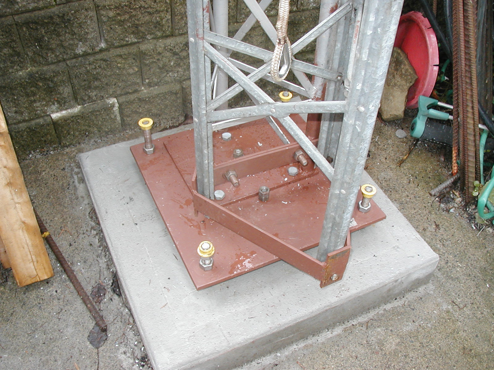 Here we see the completed base assembly showing how the base plate is secured to the
threaded rod anchors ( nuts above and below the plate to allow adjusting for plumb )
and the fixed tower base plate bolted on with 5/8" galvanized bolts. The moving section of tower
is shown bolted to the fixed tower with two 5/8" bolts in the center of the photograph.
These bolts are removed when folding over the tower. Because of the geometry of the hinge point,
the tower wants to stand vertically once you get it close to vertical. To raise and lower the tower,
I tie the rope shown dangling in the top of the picture to the lower bridle. I thought of mounting a boat
winch for raising and lowering the tower, but the balance is good enough that one person on the rope can easily control
the tower movement as it rotates on the hinge assembly.
Here we see the completed base assembly showing how the base plate is secured to the
threaded rod anchors ( nuts above and below the plate to allow adjusting for plumb )
and the fixed tower base plate bolted on with 5/8" galvanized bolts. The moving section of tower
is shown bolted to the fixed tower with two 5/8" bolts in the center of the photograph.
These bolts are removed when folding over the tower. Because of the geometry of the hinge point,
the tower wants to stand vertically once you get it close to vertical. To raise and lower the tower,
I tie the rope shown dangling in the top of the picture to the lower bridle. I thought of mounting a boat
winch for raising and lowering the tower, but the balance is good enough that one person on the rope can easily control
the tower movement as it rotates on the hinge assembly.
Source Code
 OpenScad project - hb-antenna-wire-clamp.scad
 OpenScad project - hb-end-knob.scad
 OpenScad project - hb-sleeve.scad
 OpenScad project - hb-tl.scad
 OpenScad project - hb-middle-knob.scad
 OpenScad project - hb-balun.scad
 4nec2 20M element model - hb-14P100.nec
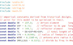 C file for generating 4nec2 model - hb-design.c

 Back to Project Index Page