 Laser Etching PCBs with Kicad, Flatcam and a 3D Printer

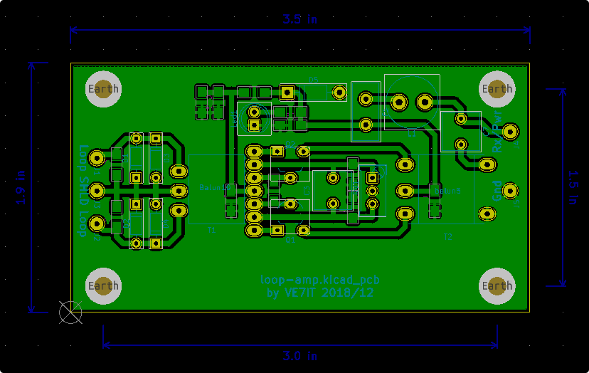
PCB Design in Kicad
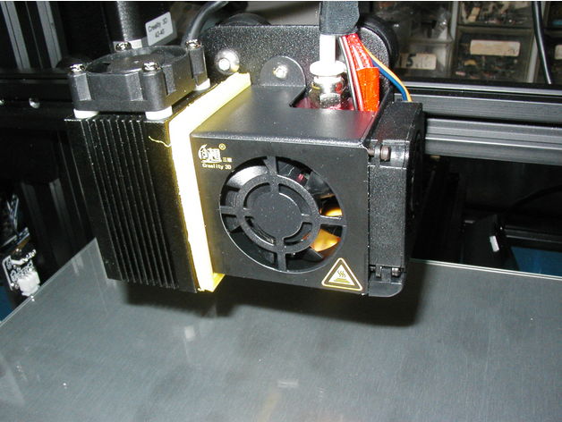
Laser mounted on Creality CR-10 mini
Project Description
This page is a series of notes describing how to make printed circuit boards from gerber files using a laser
attached to your 3D printer and a nice piece of open source software known as flatcam.
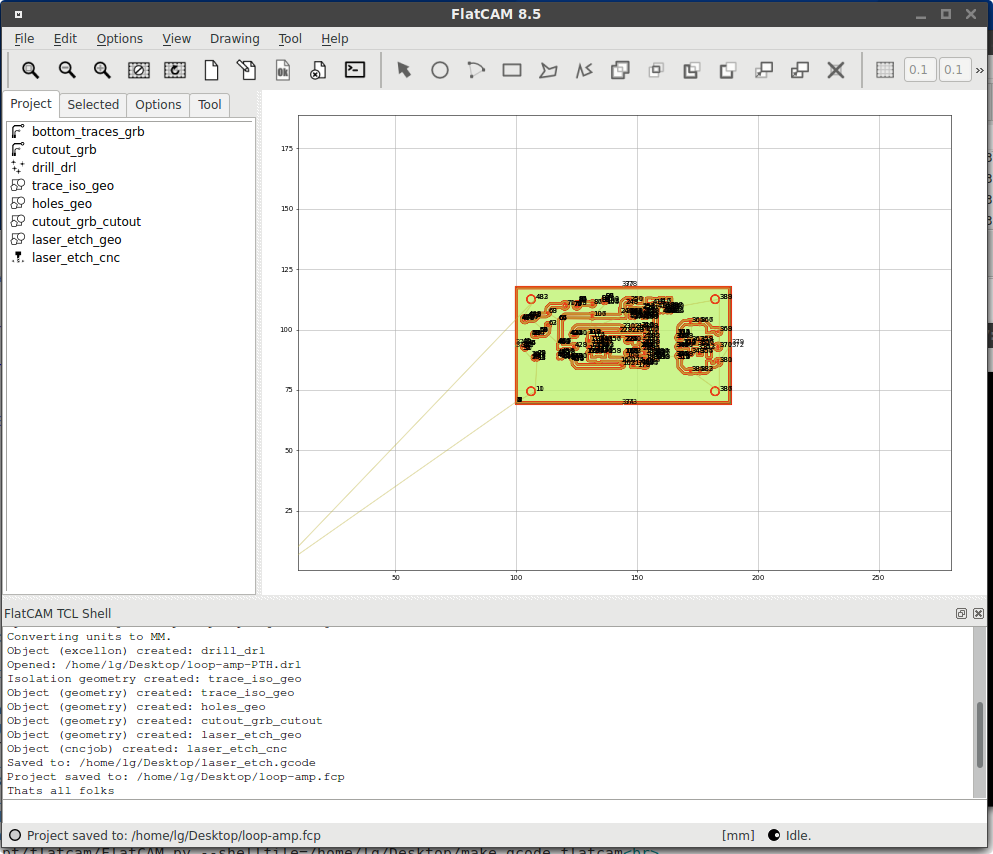
flatcam screen after running script file
From ideas to printed circuit boards takes a few steps... this is the process I use:
Kicad PCB design software-> gerber files ->
Flatcam isolation software ->
gcode machine instructions->
Repetier software to stream gcode to 3D printer ->
Creality CR-10 mini 3D printer ->
chemical etch with HCl-H2O2 ->
finished PCB
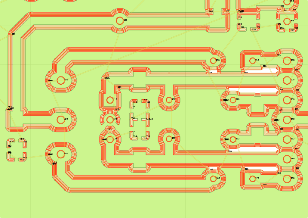
flatcam screen showing laser isolation tracks in red
To make a PCB, use your preferred PCB package such as Kicad. From you PCB software, export
your normal set of gerbers that you would send to a PCB house. This software assumes you
have designed a single sided board ( or a double sided board with only through hole parts
and wire jumpers on the top side ). The script as released uses 3 gerber files: the bottom copper traces,
the excellon drill file and the cutout profile. The script file needs to be modified to point
at these 3 files. There are a few variables defined at the top of the script file (make_gcode.flatcam)
that should be adjusted to fit your system. Sample files are given below so you can test out the
script and gcode generation.
This is the linux command line I use to start flatcam with the path to the script file:
python2 /opt/flatcam/FlatCAM.py --shellfile=/home/lg/Desktop/make_gcode.flatcam
In a few seconds, you will have a gcode file generated for your laser engraver. It is possible to generate
the same gcode from within the flatcam gui, but there are many steps and parameters required that are automated by the script.
The basic process involves importing the 3 gerber files, mirroring and shifting the geometry, generating trace isolation geometry,
generating hole marking geometry, generating cutout geometry, combining the geometry
so that one gcode file will be generated, creating a cnc job from the geometry files, and writing out the gcode.
I still have some experimenting to do to find a good reliable resist to apply to the PCB, feedspeeds for the laser etching,
board etching mixture and board drilling options.
PCB Design Ideas
For making homebrew PCBs, I like to use a combination of through hole and surface mount parts. Resistors and small caps are usually
surface mount parts and mounted on the bottom side. Through hole parts can be used to jump across traces and eliminate top surface
jumpers. I like to use 0.040" traces where possible. These are very sturdy and tolerant of home production issues. If I have to use vias
to run traces on the top surface of the board, these can become jumper wires as long as the traces dont run under top mounted parts. Its a good
idea to use large vias if you have room. The extra copper is more resistant to drilling errors and easier to manually solder.
I tend to use 1206 size surface mount parts as I have quite a good selection and they are easy to hand solder onto the board.
A liquid flux pen is very useful for coating the bare copper before soldering. My vision isn't as good as it used to be, so I have a 10X binocular
microscope I use for soldering small parts in place. I like to use a flood fill ground plane on the bottom side. This make routing grounds
easier, should make lower noise boards, makes the board look good, and saves on etchant.
Details on etching with hydrochloric acid and hydrogen peroxide can be found here:
chemical etch with HCl-H2O2
System Requirements
- A 3D printer, a laser etching machine, or a CNC router.
- A 0.5W 405nm UV laser diode package.
- Flatcam 8.5 patched with code listed below.
- Single sided PCB material coated with thin paint such as Krylon brand spray paint.
Source Code
patch file for /opt/flatcam/camlib.py - camlib.diff(8.8K)
patched version of V8.5 camlib.py - camlib.py(145.8K)
script file for flatcam - make_gcode.flatcam(5.6K)
sample board outline gerber file - loop-amp-Edge.Cuts.gbr(0.890K)
sample bottom copper gerber file - loop-amp-B.Cu.gbr(92.9K)
sample drill gerber file - loop-amp-PTH.drl(0.926K)
sample generated gcode file - laser_etch.gcode(763K)
 Back to more good stuff...