 Emergency Lightbar Controller

Project Description
This project has currently completed the prototyping phase and is waiting for production approval.
Two different versions of the project were produced. The first prototype was a 24 output
project using a PIC 16f627 microcontroller to read a panel of operator input switches and
to control 16 to 24 high current outputs used to drive a variety of lamp options on a roof
mounted light bar. The circuit supports up to 24 FET outputs for controlling leds, lamps or relays.
Each output is an open drain and the sink capability is dependant on the output FET used and the
amount of heatsinking used when mounting the FETs.
The second prototype was designed as a single sided 8 output device that could be used as a portable
warning device for construction vehicles. It was designed to be mounted inside the rear window of
a pickup truck and plugged into the cigar lighter.
This light controller project was conceived by Ted Maczulat VE7TFM (t.maczulatATshaw.ca). Ted also built the
24 output prototype.
The electrical design and PIC coding was done by Lawrence Glaister VE7IT (ve7itATshaw.ca). Lawrence built
the 8 output portable device.
This project came together as a way to integrate commercially available
high intensity led modules, second hand mechanical lightbars and some of the local electronic and
computer programming skills available from the development team. The information
on this page is presented as a means of documenting this project and a way of sharing it with the
rest of the internet.
At the present time, there are no plans to market circuit boards, kits, parts or complete light bars
for sale.
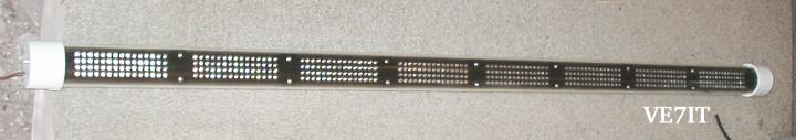
Complete 8 Segment Lightbar Assembly
This single sided version of the lightbar was constructed using a 3/16" plexiglass
strip drilled for the 480 LED's (4x15x8 segments). This strip was then slide inside
a four foot long 2"OD clear plastic tube and capped with PVC pipe caps bored out to fit the OD of the tube.
A CNC drilling machine is very useful for doing a nice job of the LED mounting strip.
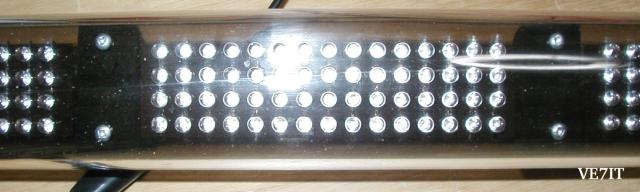
Front View Closeup of LED Matrix (4x15)
Each LED segment consists of 15 columns of 4 LEDs. Each column is in series with a 180 ohm
resistor. The 5mm LEDs fit snuggly into a 3/16 hole. Note the screws holding the semicircular
plastic spacers in place.
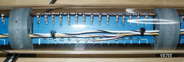
Rear View Closeup of LED Matrix
After wiring each of the leds in series, a strip of insulation (Formica) was placed on top
of the solder connections and the LED leads were wrapped around the edge. The positive
connections of the LEDs are wired to the 12 volt bus via the 180 ohm resistors. The negative
connections on the LEDs are connected together and are grounded through the FET switches on the
controller board. Each LED segment has 2 connections... the positive bus and a wire running
back to the controller CPU board in the end of the tube.
The semicircular spacers were cut out with a hole saw from a piece of 1x6
plastic board (decking from the lumber yard made from recycled plastic).
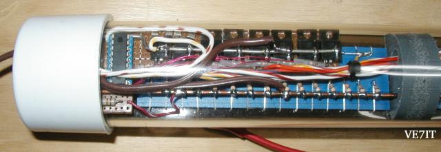
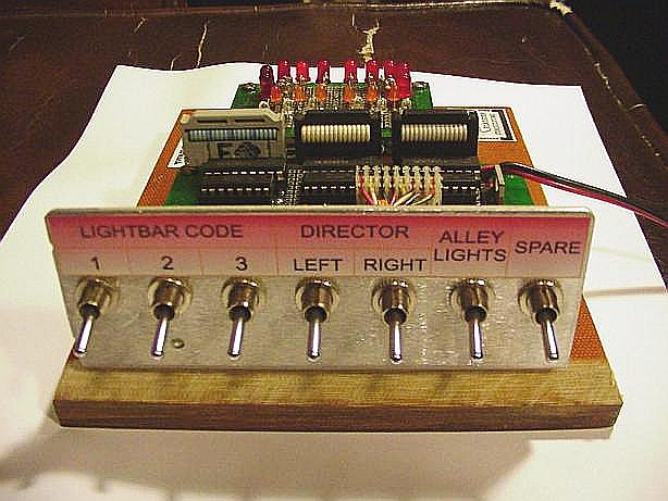
CPU Board
The CPU board was a tight fit. The CPU chip is on the left and the 8 FETs are in a row
along the rear of the LED array. The push button switch to cycle through the modes
is mounted on the PVC endcap. The power cord runs out the endcap to a lighter plug so the
lightbar can be used in any vehicle as a warning device.
The 8 Output Controller:
The 8 output controller has only one push button to select the operating mode.
The modes are as follows:
- Mode 1: Cycle through 6 attention getting non directional patterns.
- Mode 2: Left directional signal.
- Mode 3: Right directional signal.
- Mode 4: Split directional signal.
- Mode 5: Simulates a rotary lightbar with strobes.
- Mode 6: 3 segment moving display (night rider).
- Mode 7: Off.
- Mode 8: Off.
8 Output Controller Project Files
Eagle 4.11 PCB drawing file - lightbar.sch(211K)
PNG Image of Drawing - lightbar8.png(28K)
PIC assembler source code - lightbar8-revb.asm(31K)
PIC hex file - lightbar8-revb.hex(3.7K)
The 24 Output Controller:
The switches functions are listed below:
- Code 1:
Cycle through patterns flashing on rear only. Director inputs will override this.
- Code 2:
Cycle through patterns on front and rear with the rear pattern replaced by director if director switch inputs are active.
- Code 3:
Cycle through patterns on the front and rear and flash the alley lamps. Director inputs are ignored.
Directional Control (director):
- Left
The left director input is made active by switching 10-15 volts onto the left input.
The left arrow mode displays a chasing pattern across the full
width of the rear of the lightbar, indicating to traffic to proceed around
the emergency vehicle to the left.
- Right
The right director input is made active by switching 10-15 volts onto the right input.
The left arrow mode displays a chasing pattern across the full
width of the rear of the lightbar, indicating to traffic to proceed around
the emergency vehicle to the right.
- Split
To activate the split mode, both the left and right inputs are pulled to 10-15 volts.
The center out arrow mode provides a chasing visual display conveying
to traffic to merge around either side of the emergency vehicle.
24 Output Controller Project Files
Autocad drawing file - lightbar.DWG(56.9K)
Postscript of Drawing - lightbar.ps(217.6K)
PIC assembler source code - f627-lightbar.asm(30.7K)
All project files (source, dwg, listing etc) in linux compressed tar format - f627-lightbar-04aug2003-src.tgz(64K)
System Requirements
The source code can be compiled using the free microchip IDE environment under windows or
using the gp_utils package (gpasm assembler) under linux. The PIC microcontroller is programmed
using the in circuit programming capabilities of the PIC chip. You will need to build or buy
an in circuit programmer that supports the 16F627. See PIC
16F627 programmer and software for Linux.
 Back to Lawrence's Software Stuff Page