 Cable and Mods for Using 2 Maxtrac Radios as a Repeater

Project Description
This project is a radio interface cable that is used to connect 2 Maxtrac/Radius
models of Mototola VHF and UHF two way radios in such a way that they can be used as a repeater.
Mods are done inside the radios to bring a conditioned COS/COR signal out through the mic connector.
The cable pinout uses the standard defined by Link Communications in their RLC-4
repeater controller. In an emergency, a jumper from COS to PTT and a resistor/cap from the
RX audio to the TX audio lines would yield a repeater (no IDer, so be aware of your local regs).
In this setup, one radio is used as a receiver and the other as a transmitter. If both
radios are programmed the same, one has a redundant system where the rx and tx can be swapped
by moving the mic cables and the antenna connections. Note that Maxtrac radios are not designed for
long key down times and they will get VERY hot if you do not use a fan to cool the transmitter
heat sink. It is also recommended that you reduce the transmitter power setting using the RSS software
for the radio. The COS signal modification brings out what is basically the audio mute signal.
If the mode is setup using PL tone, the output can be used in 2 ways. The first gives you a
"PL and COS" indicator and the second method for "COS only" can be activated by pushing the monitor button
on the front of the radio. I have modified 4 slightly different versions of radios and am currently
running this system on IRLP node 1130 (UHF 444.300/449.300 with a 141.3PL tone) and on the
local club repeater. (VHF 147.080/147.680 with a 141.3 PL tone).
Typical Radio Modification To Bring Out COS
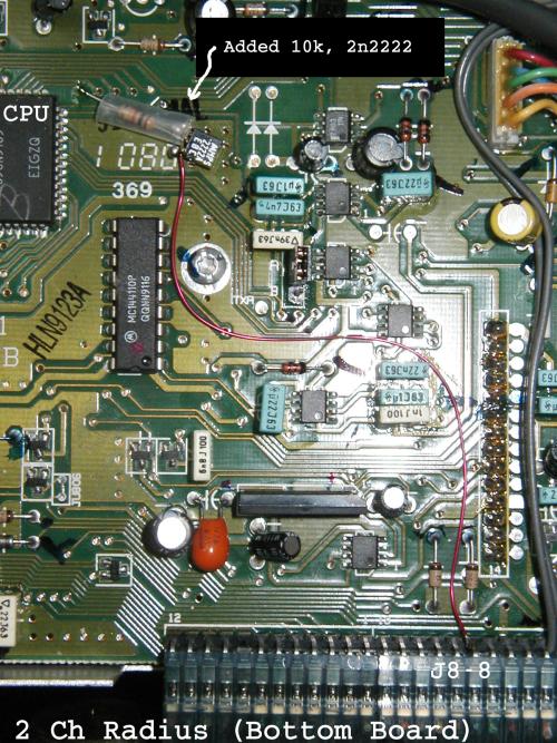
The above picture is the bottom (logic) board in a 2ch Radius D34LRA73A5CK.
The solder mask must be cleaned off the feedthrough and part of the ground plane
under the added transistor. One end of the 10k is soldered into the via, the
other end is soldered to the base of the transistor. The emitter of the
transistor is bent down and soldered to the ground plane. The collector of the
transistor is jumped to J8-8 with wirewrap or similar wire. This open collector
signal then pulls pin 1 of the mic connector to ground whenever the audio gate
is opened. Note that this mod makes all signals for linking available on the
mic connector. It does not matter if the radio has the 5 pin or 16 pin logic
board. See the drawing below for several different logic board mods. The handset
audio on the mic connector is a constant level and is not affected by the volume
control. You can still use the internal speaker for monitoring radio operation.
System Requirements
A computer running Motorola RSS software for the radio that is to be programmed,
a compatible radio and the cable.
Electrical Drawing(s)
Drawing File - maxtrac-rptr.png(14K)
Source Code
No code required.
 Back to Lawrence's Software Stuff Page