 Recycle PS/2 Mice into Rotary Pulse Generators

Project Description
This project involves killing of rodents (but no amimals were hurt during this experiment).
A rotary encoder is a very useful device for a lot of PIC microcontroller projects. There are
mechanical variants which are not very expensive (about $8) and optical versions which range upwards
from $30 to thousands of dollars depending on resolution and packaging. Being a junk collector,
I seemed to end up with a lot of old computer mice. I decided to try and recycle these mice into useful
bits for my other projects. Each mouse
has at least 2 rotary encoders so this project is an attempt to reuse and repackage these encoders into
something that can be used with a microcontroller for an input device. A typical application could be
for frequency control on a digital variable frequency oscillator or as a rotary pulse generator (RPG)
for an input device on a CNC machine.
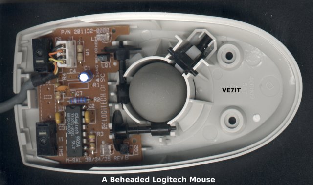
After examining several type of mice, I found there was quite a range of technology used
in the detector circuits. Some older mice used LEDs and phototransistors that required quite a bit of
support circuitry. The best units I found had an integrated detector that directly output TTL level
quadrature signals. These units had 3 pin clear plastic IR LED sources and black plastic 4 pin detectors.
I found these integrated detectors in various samples of Compac, HP and Logitech mice.
To interface to a microcontroller, all that is needed is one output pin to pulse the
infrared emitter and two inputs to read the 2 phases of the encoder. There is an interesting characteristic
of the internal mouse controller. The LED sources are pulsed on by the controller about 120 times per second
( 14.8us on, 8.5ms off ).
When motion of the encoder wheels is detected, the pulse rate increases up to over 5000 times/second
( 14.8us on, 172us off ).
This operation results in three benefits. The LED life is improved, the current consumption
of the mouse is minimized when it is not being used and the signal to noise ratio on the
detectors is improved
because the LED sources can be driven harder when using a 8.6% duty cycle.
The source detector pair was tested with a 330 ohm series resistor on the source LED.
The result is about 9ma of current flow and the detector performed beautifully in normal
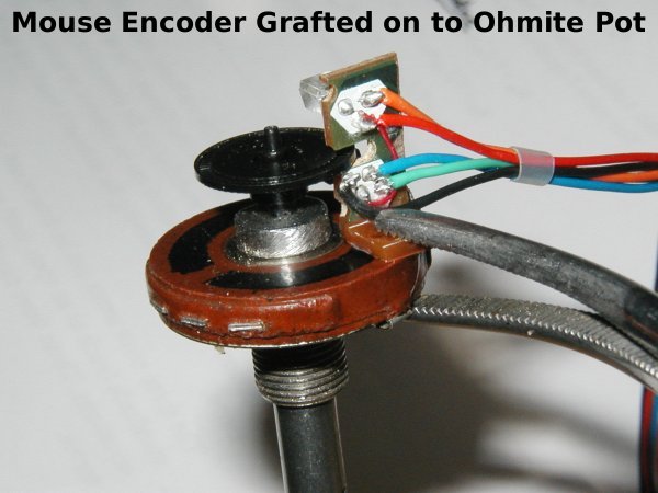
office lighting. The new encoder source/detector pair is mounted on a hacked Ohmite 2 watt potentiometer.
The stub shaft was threaded for 10-32 and a nut was screwed on to hold the shaft in the
pot panel bushing. The nut was held on a grinder to reduce its diameter. It was locked in
place with a little drop of crazy glue (dont get it in the moving parts!). The source/detector
pair was clamped to the pot to get it aligned with the slots in the encoder wheel. Once
everything checked out on a dual channel scope, another drop of glue was used to fasten the
source/detector board to the rear of the pot (see photo 1).
Features
- Low cost rotary pulse generator
- Resolution of around 256 pulses/revolution
- Pulse rates of up to several hundred pulses/second
- Keeping old mice out of the dumpster
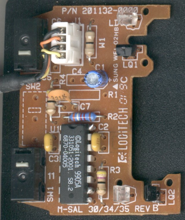
Close up of the top of the circuit board.
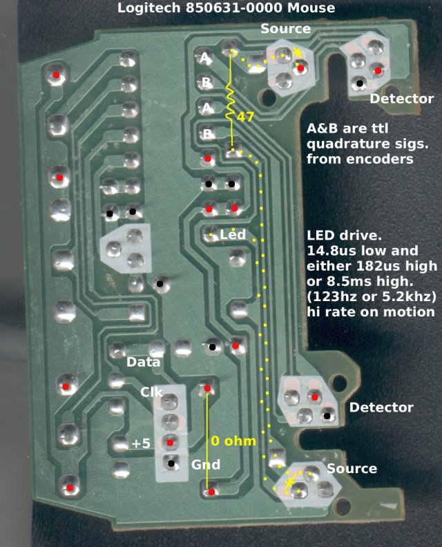
Bottom of circuit board showing source and detector paths. Ground and 5 volt
signals are detailed with black and red dots.
System Requirements
- A selection of beheaded mice
- HP mouse P/N 5182-8864
- LogiTech mouse P/N 850631-0000
- Compac mouse
- Old 2Watt potentiometers
Electrical Drawing(s)
None
Source Code
None required.
 Back to Lawrence's Software Stuff Page