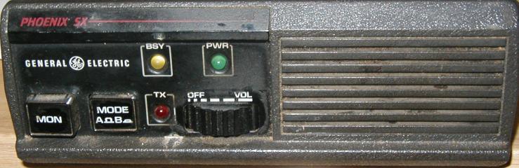
 GE Phoenix SX EEPROM Conversion
GE Phoenix SX EEPROM Conversion
![]()
![]()
![]()
![]()
![]()
This is an intel hex file dump of a test image I
used in a 2 channel Phoenix SX.
The settings are:

Ch A Rx = 150.000 141.3hz tone, Tx 151,000 100hz tone
Ch B Rx = 140.000 141.3hz tone, Tx 141.000 141.3hz tone
CCT timer 1 minute, 5khz ch spacing, and a 13.2Mhz reference

 :100000000F080F0F0F0F000000080F0F0F0F000059
 :1000100000090C02080305010000070E0800050195
 :10002000000A000308090501000A01020800050191
 :1000300008000B0E080B0B0008000C0D0802050150
 :1000400000080F0F0F0F000000080F0F0F0F000028
 :1000500000080F0F0F0F000000080F0F0F0F000018
 :1000600000080F0F0F0F000000080F0F0F0F000008
 :1000700000080F0F0F0F000000080F0F0F0F0000F8
 :100080000F080F0F0F0F000000080F0F0F0F0000D9
 :1000900000080F0F0F0F000000080F0F0F0F0000D8
 :1000A00000080F0F0F0F000000080F0F0F0F0000C8
 :1000B00000080F0F0F0F000000080F0F0F0F0000B8
 :1000C00000080F0F0F0F000000080F0F0F0F0000A8
 :1000D00000080F0F0F0F000000080F0F0F0F000098
 :1000E00000080F0F0F0F000000080F0F0F0F000088
 :1000F00000080F0F0F0F000007080F0F0F0F000071
 :00000001FF
Notes on UHF Phoenix code changes - phoenix-uhf-changes.txt(3.5K)
![]()
Phoenix Microphone Connector (P911)
The 8 circuit terminal housing:  0.156 for J911 is Digi-Key P/N WM-2106-ND
Pins for housings are Digi-Key P/N WM2300-ND

P911  Description
1   GROUND (A-)
2   PTT - TX  (Active LOW)
3   MIC SHIELD GROUND
4   MICROPHONE INPUT HI
5   MICROPHONE INPUT HI
6   RESET (Active LOW)
7   CHANNEL SELECT
8   (I converted this pin to +12V for mic power)


Phoenix Power Connector (P910)
The 11 circuit terminal housing: 0.156 for J910 is Digi-Key P/N WM-2109-ND
Pins for housings are Digi-Key P/N WM2300-ND

P910  Description
1   TO IGNITION SWITCH + (2A Fused)
2   RX MUTE (Active LOW)
3   EXTERNAL SPEAKER HI
4   FILTERED VOL/SQ HI
5   SPARE (Channel A/B Select)
6   GROUND
7   EXTERNAL SPEAKER LOW
8   GROUND
9   CG DISABLE (Active LOW)
10   INTERNAL SPEAKER HI
11   +13.5 VDC POWER INPUT (15A Fused)
![]()