
One Tube Regen Retro BCB Radio

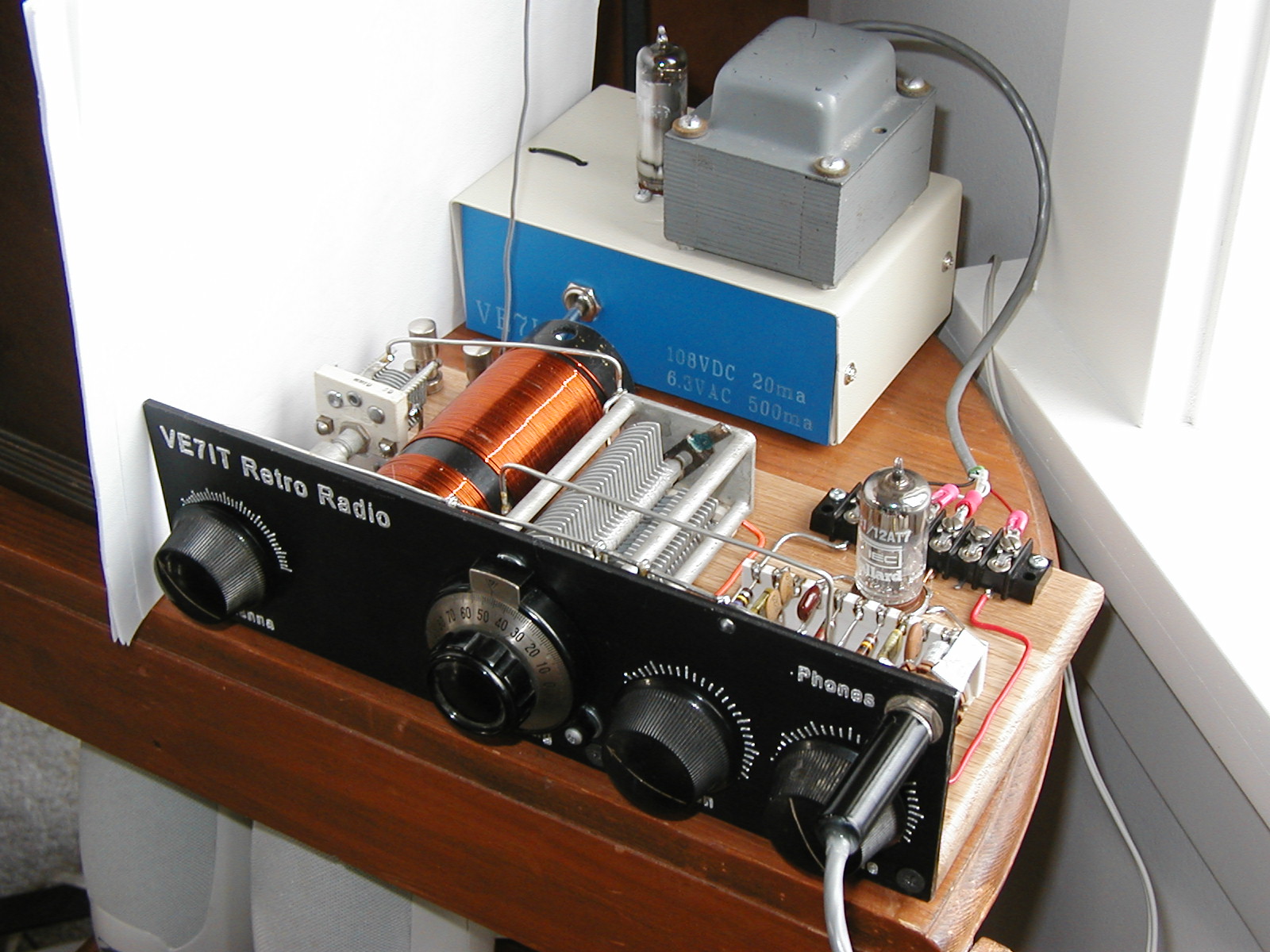
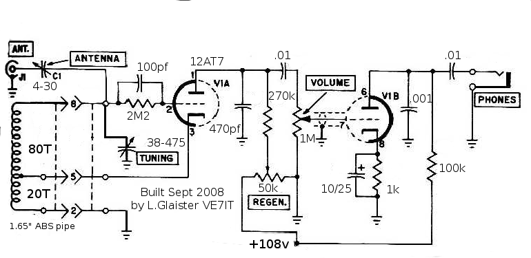
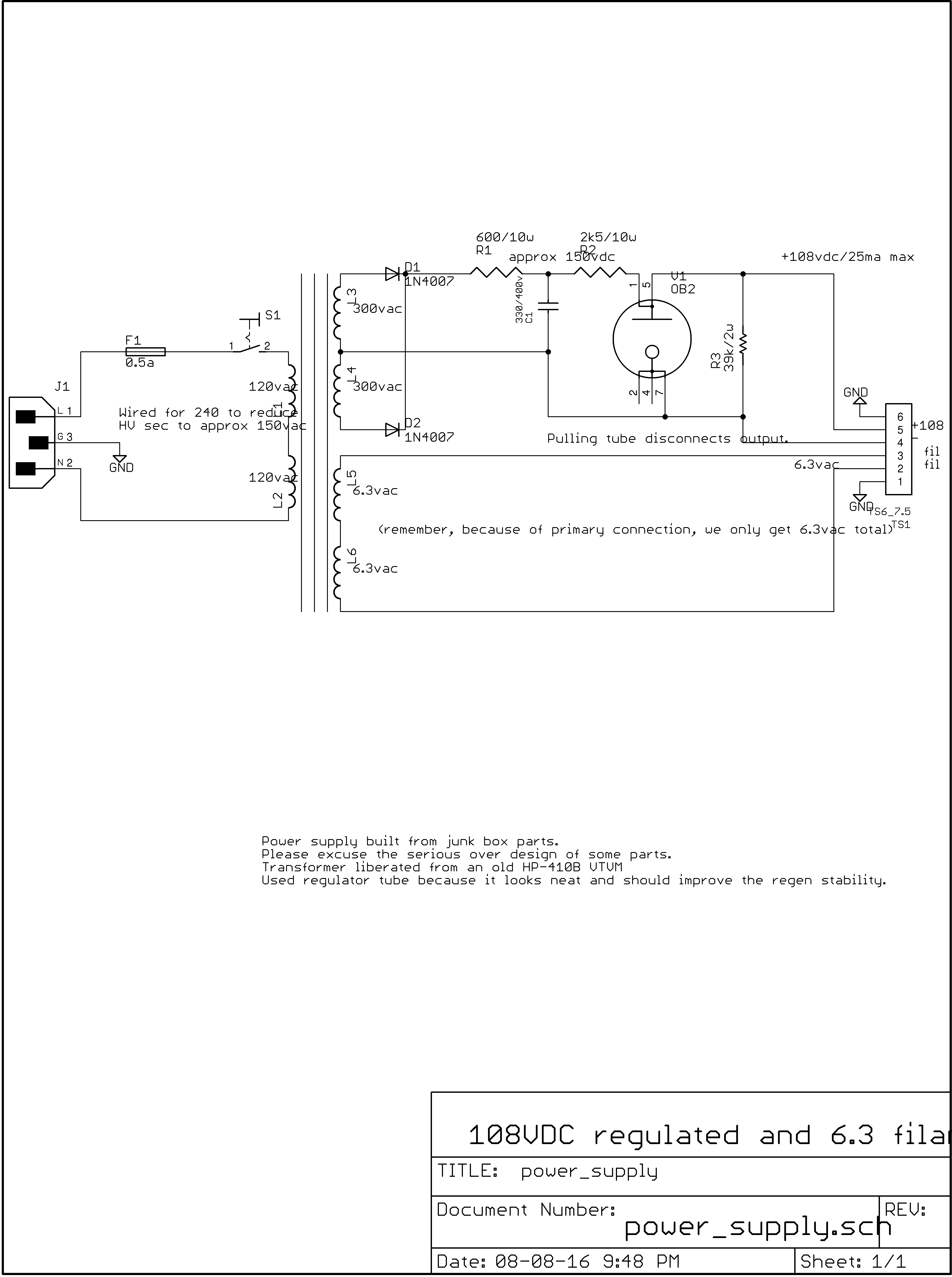
This project re-creates a single tube regenerative receiver typical of those used in the 1930's and 1940's. After WWII, the superhet style receivers came to be much more commonly used. This project uses a dual triode tube (the part is very non critical), using 1/2 the tube as the active RF portion and the other half as an audio preamplifier. An external power supply is used to supply 6.3 volts A/C for the filament (heater) and regulated 108V DC for the tube plates. This circuit uses a Hartley oscillator design distinguished by a tank circuit consisting of a tapped coil in parallel with a capacitor, with an amplifier between the relatively high impedance across the entire LC tank and the relatively low voltage/high current tap point between the coils.
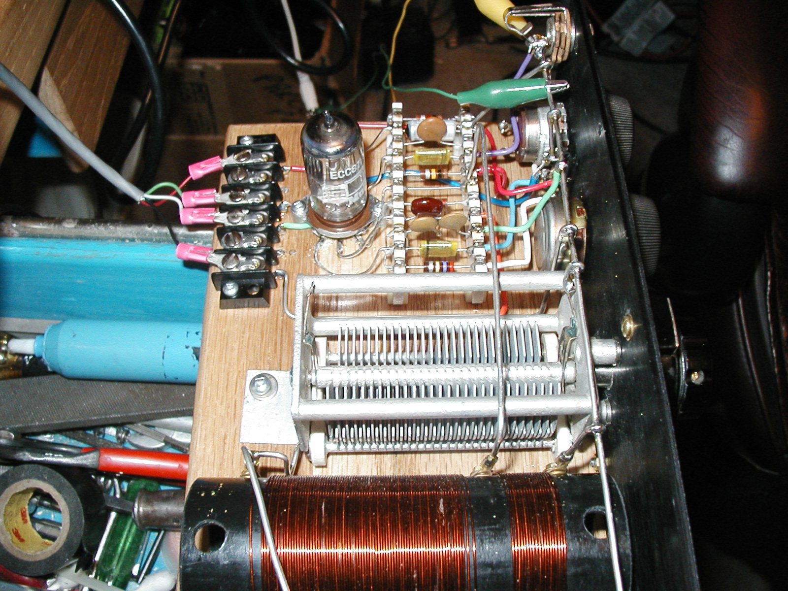
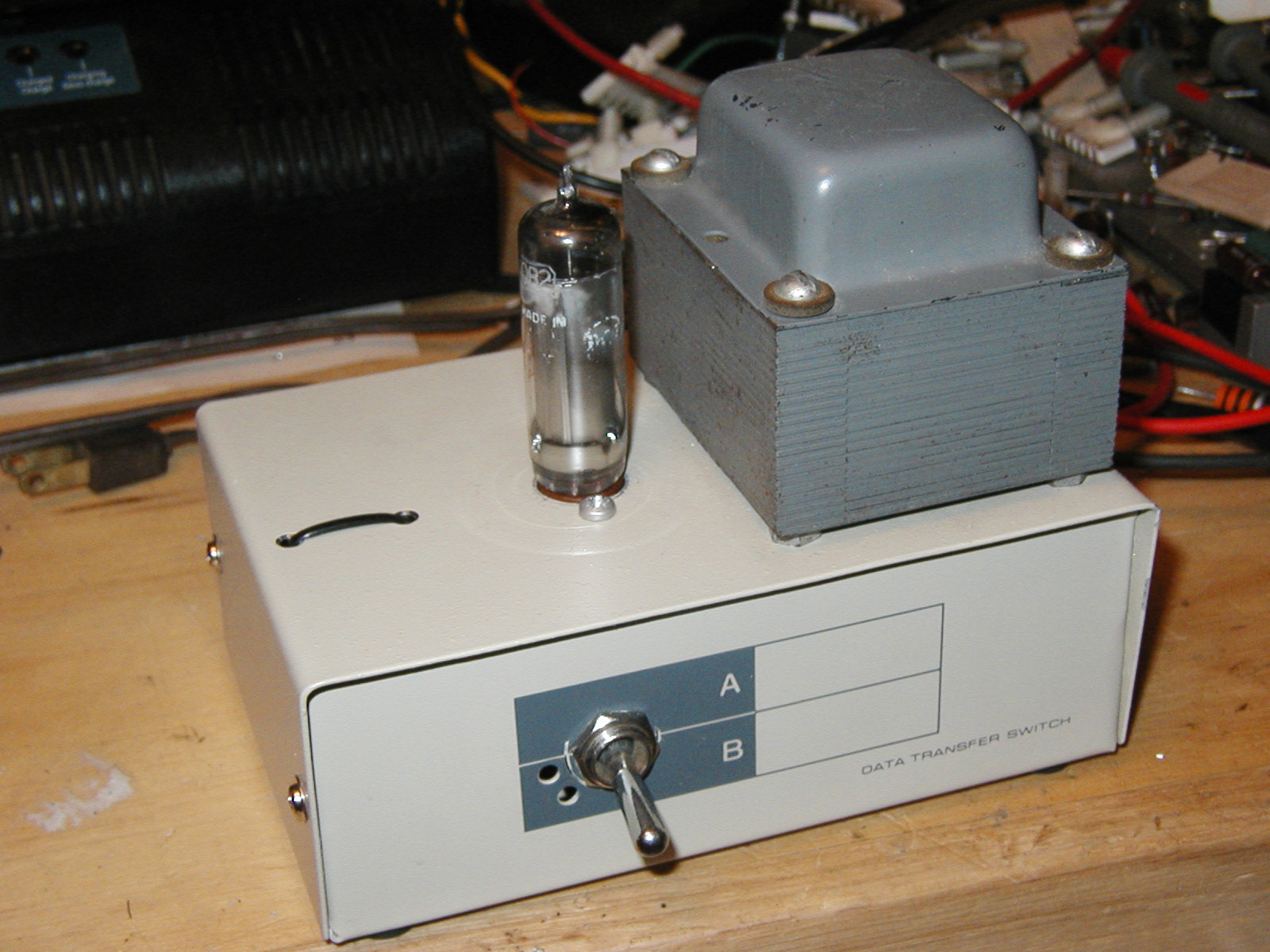
Most parts for this project were scrounged from the junk box. Variable capacitors came from long ago disassembled WWII equipment, the ceramic terminal strips were from a junked Tektronix oscilloscope, the coil was wound on a piece of ABS drain pipe, the chassis is a block of oak plank and the front panel was some recycled equipment panel engraved with control labels. The power supply was built on a box that used to contain a 2 position parallel port printer switch from the DOS days. I had a regulator tube, and I liked the purple glow, so I built a regulated supply to supply the high voltage to the radio. Since a regenerative receiver is basically an oscillator, using regulated voltage helps maintain good frequency stability.
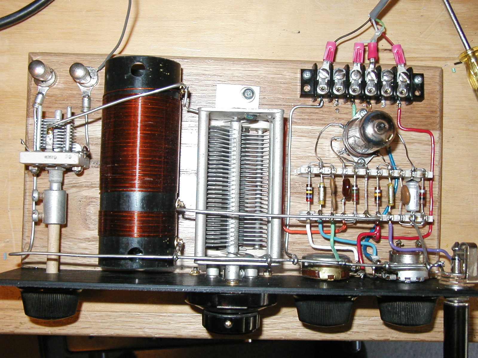
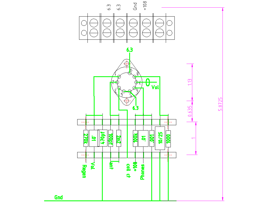
The layout drawing above was used to used to figure out a nice clean way to organize a lot of the small parts. This replaced the modern day PCB layout and design step.
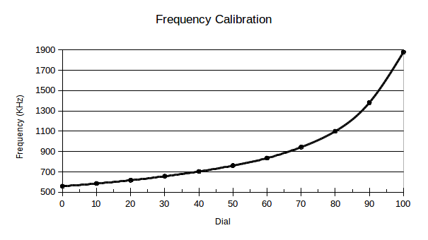
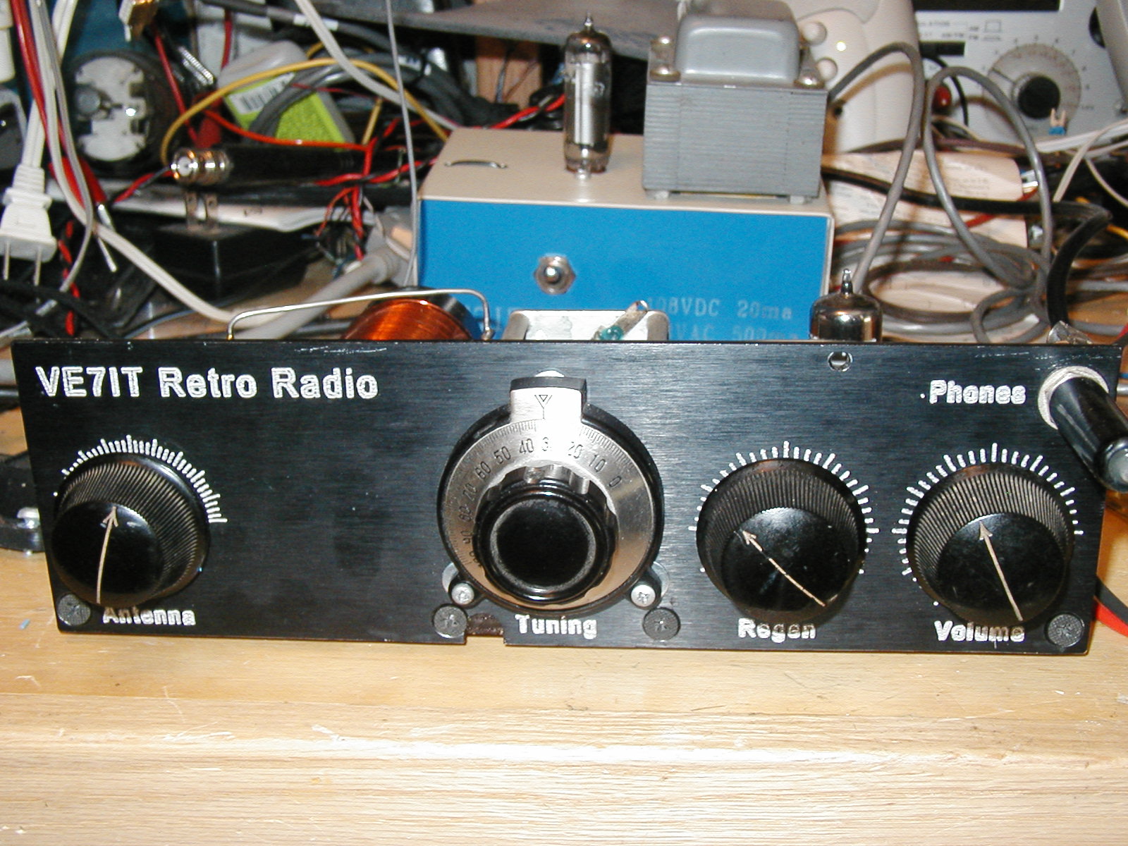
The receiver as built does not have a frequency display. It has a 0-100 scale on the vernier control used to turn the main tuning capacitor. I generated the calibration chart by setting the the vernier to each of the major divisions on the dial. By setting the regeneration control up to the point where the detector oscillates, I was able to use a frequency counter to determine the actual tuned frequency. A few quick entries into a modern spreadsheet results in a nice calibration chart that is printed and attached to the bottom of the radio.
Using the receiver involves plugging in a set of high impedance headphones or in my case, I used a set of powered computer speakers that contains an amplifier and speakers. Attach an antenna (10' of wire should get you started). Power up the power supply, adjust the volume, and play with the regen control until you notice a change in the noise as it breaks into oscillation. Set the regen control to a point just before oscillation. This will result in the most sensitive point of detection for AM broadcast band signals. Adjust the tuning capacitor until you find a signal. Once you can hear a signal, you can tweak all the controls until you get a nice sounding signal at a comfortable volume. Using the radio involves optimizing several settings: antenna coupling, tuning, regeneration and volume control. It becomes very intuitive after a little bit of operation. This is a real radio with real controls... dont be afraid to twist the dials and explore the operation of the receiver.