

Project Description
This project has returned me to the fun times of computing in the 1970's. Building an Imsai processor system in my spare time while struggling through engineering school launched my career in industrial automation and controls. I was recently given some S100 hardware that I really wanted to get operating again. Perhaps my 40+ years of experience (or more likely the vast amount of information now available on the internet) made this a fun and rewarding way to pass the time during all the covid restrictions.
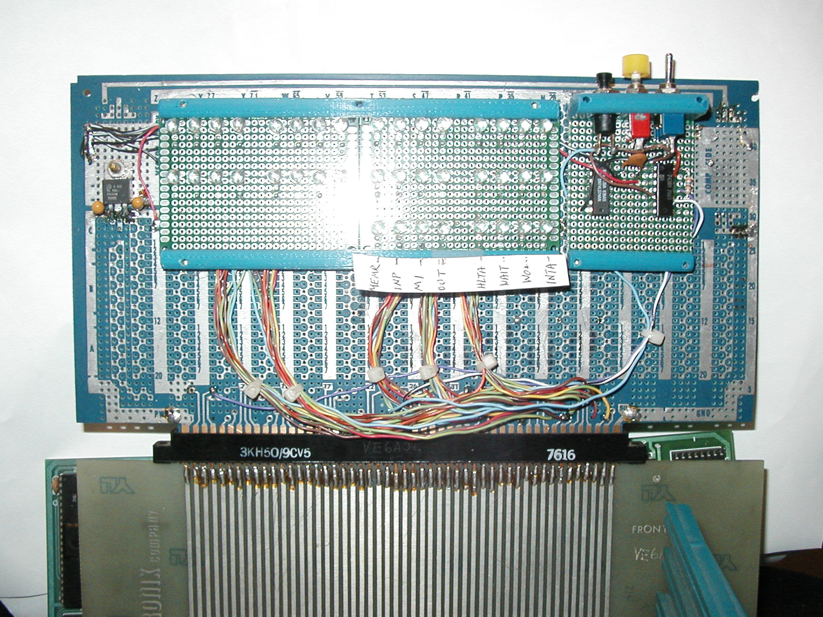
This project started when I was trying to understand why the S100 hardware was not starting up properly. There where lots of signals on the bus and lots of activity on the processor pins, but I could not get an overall picture of what has happening. The project started with adding leds to most of the S100 bus address, data and status lines. This helped, I could see the processor was running, but I still could not get it to run as expected. The second stage of the project was to add a run/stop switch and some logic to enable single stepping the Z80 processor. This project is not a full front panel like the Altair or Imsai systems, but just enough to get things working. It does not support memory examination or deposits, or starting execution from a specified address. The goal was to get an eprom monitor running that could be used to do these things and much more. I did not buffer the bus signals driving the leds. With the 680 ohm resistors and bright leds, the bus signal load is only 5ma. Most cards use bus drivers capable of 24ma. Consider the loading as simple bus terminators.
Construction was done on small prototyping boards which were mounted on an old S100 wire wrap board. One could easily strip any old S100 board and bolt on this projects hardware, using just the bus connector and possibly the existing 5V regulator. Several plastic parts were 3D printed to hold the various pieces, but bolts and standoffs or even hot melt glue would suffice.
Success at last!. This project did help get the S100 Z80 hardware operational. Using the single step operation, I watched the program jump to the rom monitor code and start to execute things properly. The instruction execution worked as expected until the first jump instruction was encountered. The jump never happened. It turns out the Z80 CPU was damaged and would run, but would not perform any jump instructions. Replacing the CPU chip with a spare made everything work as expected.
System Requirements
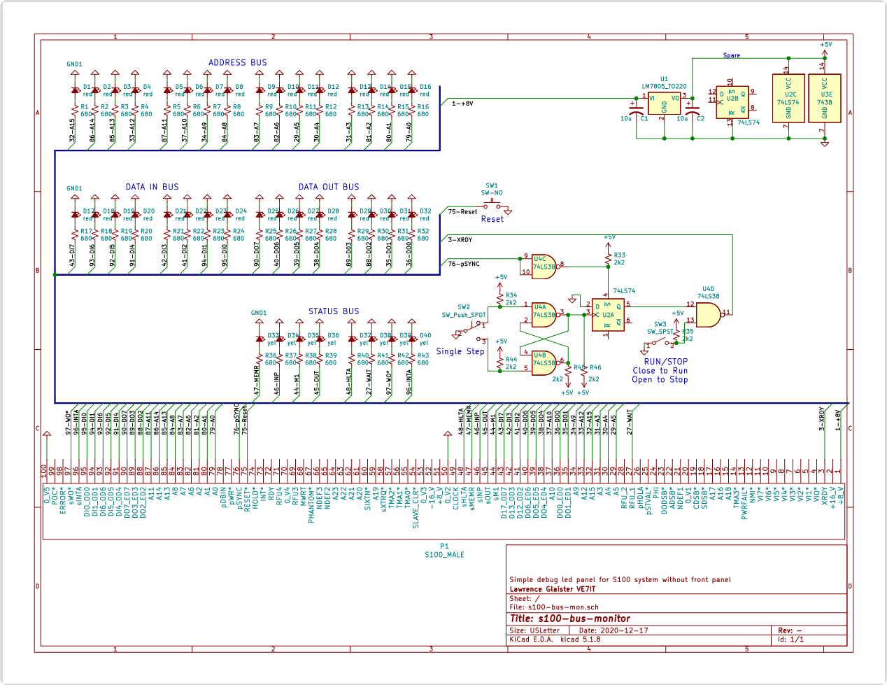
This project is useful in just about any S100 bus system. A basic S100 system consists of an S100 backplane, +7.5V and +-15V power supplies, a processor card, a memory card and support for a serial port and eprom monitor (may be on the processor card or other S100 cards). Additionally you will probably want some type of floppy or mass storage system so you can run CPM (the operating system of a lot of the 70's microprocessors).Electrical Drawing(s)
Schematic File - s100-bus-mon.pdf (110kB)Kicad Schematic - s100-bus-mon.sch(54K)
Source Code
OpenScad project - 3D model code for control board mounting(3Kb)OpenScad project - 3D model code for led board mounting(1.5Kb)
![]()