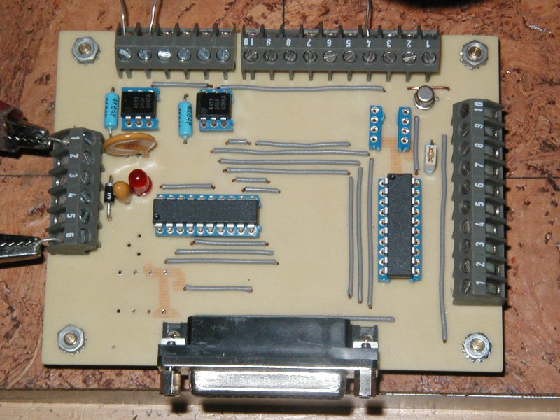
 Buffered Parallel Port Breakout Board

Project Description
This project is used with the EMC2 CNC controller software package.
The board was built for my Shoptask lathe/mill/drill machine.
The board provides
- a pulse driven watchdog interface (used to hold in the main control power relay)
- a PWM output to drive a variable speed spindle
- isolated inputs for external estop status and a probe
- 8 bits of buffered bidirectional I/O (source or sink 24ma) that can be used as 4 channels of step/dir
I/O or as 8 inputs
- outputs to drive solid state relays for spindle power and mist coolant
- three buffered inputs for a
lathe spindle encoder with A,B,Z channels)
System Requirements
25 Pin parallel port interface on the computer, CNC controller software using the parallel port.
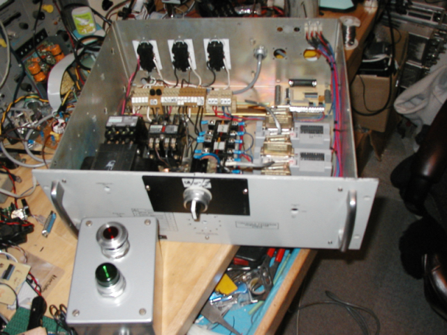
A very messy bench with the remote pendant, stepper drivers, contactors, SSR's and the breakout board.
Electrical Drawing(s)
Schematic Drawing - bob-lg-sch.png(58K)
PCB Connections - bob-lg-brd.png(53K)
Eagle PCB file - BOB-lg.sch(268K)
Eagle PCB file - BOB-lg.brd(44K)
Sample Power Wiring- bob000a.pdf(110k)
Questions and Answers
Q. in the Eagle files, a lot of SMD components are showing, but can't be seen in
the photograph of the BOB.
A. Sorry, I did not take a photograph of the bottom of the PCB.
If you use the eagle files, you can see from the red or blue colors,
what parts are on the top or bottom of the board. Since I started using SMT parts,
I really like having all the resistors and caps on the bottom of the board.
I sometimes still use leaded resistors if they will help make the layout easier.
Since I use a milling machine to make my one sided boards, a lot of the design
is biased towards what my machine can do.
Q. I couldn't identify the values of C14, R9.
A. C14 is not critical.. it is a bulk filter for the incoming 5 volt supply.
I probably used 10uF/35v tantalum just because I have a bunch.
You could use a standard electrolytic... 10-100uF would be OK... pick something
that fits in the space and has close to the right lead spacing.
R9 is optional.... you can just put in a jumper. It is a poly silicon device that
acts as a self resetting fuse. I dont have the part number.
You could also put in a pico fuse of about 0.5amps if your power supply doesnt
have a fuse.
Q. I also see you have installed T1 but can't see the rest of the components, why?
A. When I took the pictures, I didnt have the MAX6303 (I was waiting for samples
to arrive). The rest of the parts are surface mount on the bottom of the board.
If your controller software doesnt require (or you dont want to configure it) an external
watchdog in the Estop loop, you can leave all the watchdog associated parts off the
breakout board.
Q. What is JP1 used for?
A. JP1 determines the direction of the 74ac245 driver chip. In most cases, you want the
chip used as an output driver for the step/dir pins. Most PC ports can also be
programmed to use the 8 bits as inputs... if you need
inputs and not outputs, the jumper can be set so the 74ac245 acts as an input
buffer instead of an output driver.
 Back to Lawrence's Software Stuff Page