
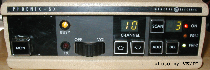
GE Phoenix SX X2212 Programmer

![]()
tar -xzvf ge-x2212-2-27sept-2004.tgz
cd ge-x2212-2
./autogen.sh
make
sudo make install
If you have problems building with autotools, the glade project notes may help.
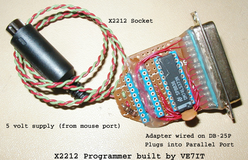
                        X2212 programmer schematic

Parallel port                                      X2212 / X22C12 eeprom

2 (D0) ------------+---------------------------------------- 6  (A0)
3 (D1) ----------+-|---------------------------------------- 5  (A1)
4 (D2) --------+-|-|---------------------------------------- 4  (A2)
5 (D3) ------+-|-|-|---------------------------------------- 3  (A3)
6 (D4) ------|-|-|-|---------------------------------------- 2  (A4)
7 (D5) ------|-|-|-|---------------------------------------- 16 (A5)
8 (D6) ------|-|-|-|---------------------------------------- 17 (A6)
9 (D7) ------|-|-|-|---------------------------------------- 1  (A7)
             | | | |  +------------+
             | | | +--|3 d0    q0 2|-------+---------------- 12 (D0)
             | | +----|4 d1    q1 5|-------|-+-------------- 13 (D1)
             | +------|7 d2    q2 6|-------|-|-+------------ 14 (D2)
             +--------|8 d3    q3 9|-------|-|-|-+---------- 15 (D3)
                   +--|1 /OE  LE 11|--+    | | | |
                   |  +------------+  |    | | | |
                   |  74xx373 or 374  |    | | | |
1 (/C0) -----------+------------------+----|-|-|-|---------- 11 (/WE)
                                           | | | |
15 (S3) -----------------------------------+ | | |
13 (S4) -------------------------------------+ | |
12 (S5) ---------------------------------------+ |
10 (S6) -----------------------------------------+

14 (/C1) --------------------------------------------------> 7  (/CS)
16 (C2)  --------------------------------------------------> 9  (/STORE)
17 (/C3) --------------------------------------------------> 10 (/RECALL)

Also connect grounds: pins 18-25 on LPTx -> pin 10 on '373 -> pin 8 on 2212
Connect 5V to pin 20 on '373, and pin 18 on 2212. If you dont trust your
5v supply, put a 5.1v zener across the X2212 power pins and use a 10ohm
quarter watt resistor in series with the plus supply lead. This may save
the logic chips if you hook it up to 12 volts by mistake (it will certainly
let you know by letting the smoke out of the resistor!).
Phoenix Microphone Connector (P911)
The 8 circuit terminal housing:  0.156 for J911 is Digi-Key P/N WM-2106-ND
Pins for housings are Digi-Key P/N WM2300-ND

P911  Description
1   GROUND (A-)
2   PTT - TX  (Active LOW)
3   MIC SHIELD GROUND
4   MICROPHONE INPUT HI
5   MICROPHONE INPUT HI
6   RESET (Active LOW)
7   CHANNEL SELECT
8   (I converted this pin to +12V for mic power)


Phoenix Power Connector (P910)
The 11 circuit terminal housing: 0.156 for J910 is Digi-Key P/N WM-2109-ND
Pins for housings are Digi-Key P/N WM2300-ND

P910  Description
1   TO IGNITION SWITCH + (2A Fused)
2   RX MUTE (Active LOW)
3   EXTERNAL SPEAKER HI
4   FILTERED VOL/SQ HI
5   SPARE (Channel A/B Select)
6   GROUND
7   EXTERNAL SPEAKER LOW
8   GROUND
9   CG DISABLE (Active LOW)
10   INTERNAL SPEAKER HI
11   +13.5 VDC POWER INPUT (15A Fused)