 Variable D/C Supply(s) for the Workbench and A D/C Load

Note: This is not a step by step page for construction of this piece of test equipment. There are
no parts lists or even details on the various modules used. I have tried to describe the functionality
of the various parts. This web page is a collection of notes and ideas mostly for myself to document the various
parts of the build. Each builder will probably have many different ideas on what functionality is needed
to make their bench useful. I am even thinking of building another version for working with vacuum tube
projects. Several filament supplies, at least 2 variable high voltages and a variable bias supply would
be useful! Be inspired.... build something.... it really helps when you can figure out what
"gozinta and comesouta" any project you want to work on.
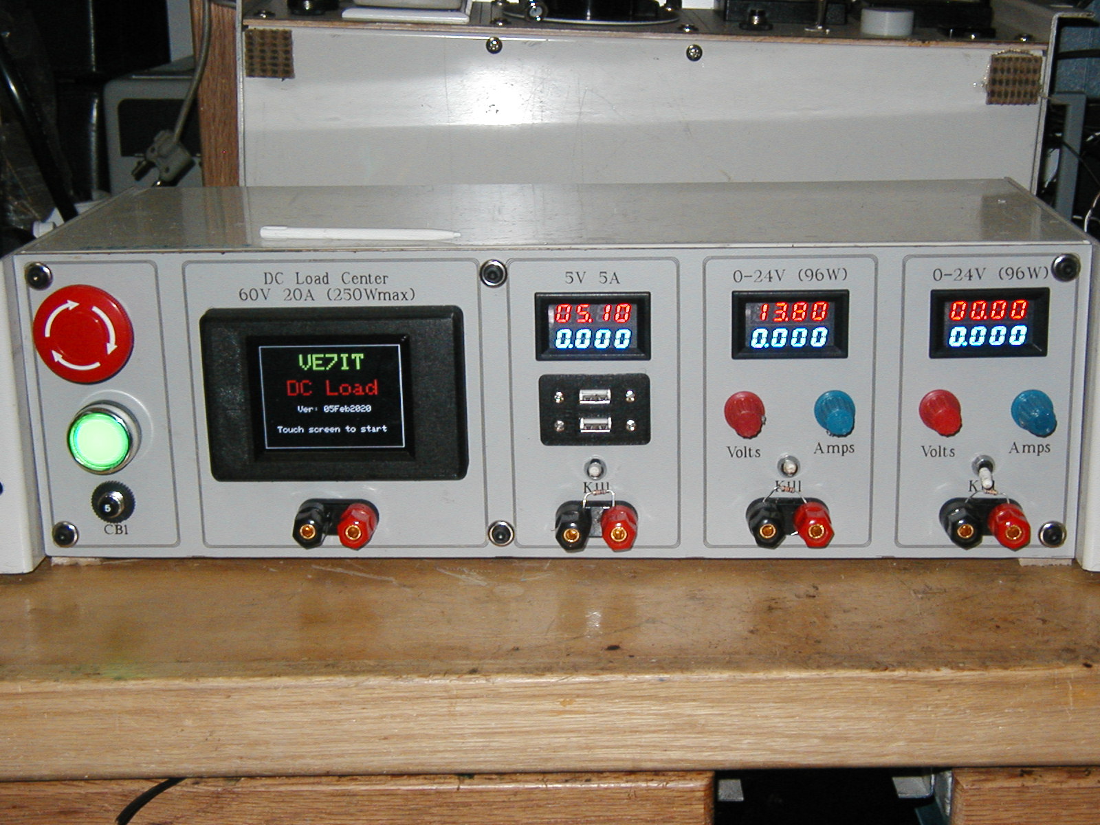
Finished Power Supply
This project was inspired by the need for a variable D/C supplies with current limiting and overload protection for use on the test
bench when prototyping circuits.
The project consists of a great collection of chinese modules and parts that together form a very useful piece of gear for the test bench.
This project just packages everything in a nice enclosure that lives on the workbench.
The project is build in a recycled 3U 19" shallow rack case from some old radio equiment. The project starts with a 5 amp circuit breaker
that protects the entire box. This feeds an industry standard stop/start station feeding a relay to provide an emergency stop feature and also
provides for a feature where the panel will stay de-energized after a power failure.
The project consists of two major sections. The DC load which acts like a programmable resistor used for testing batteries and power supplies and a
series of 3 independant floating power supplies that can be used in series, parallel or independantly.
DC Load Control
DC Load Run Screen
The DC load portion of the project uses an ESP32 microcontroller, a SPI touch display, a real time clock module, a 4 channel 16 bit
A/D board, some op amp circuitry and a couple of big power fets on a fan cooled heatsink.
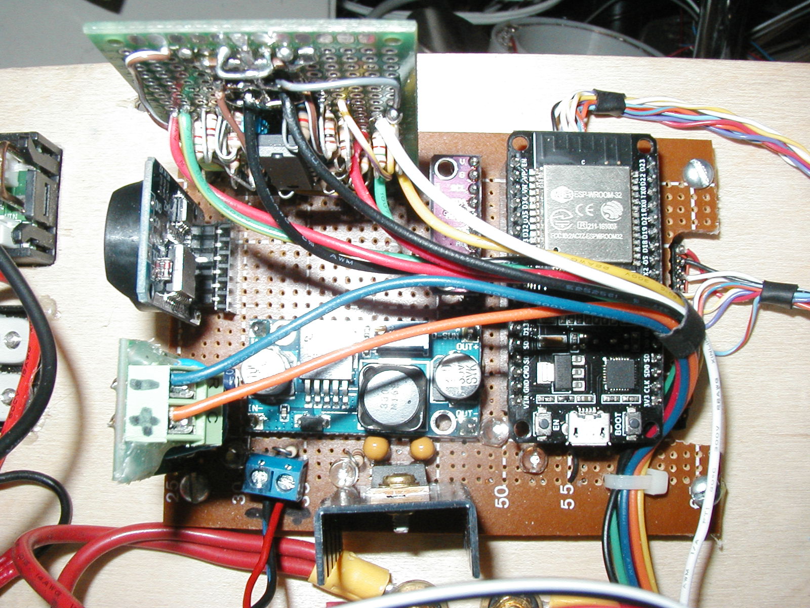
DC Load Control Board
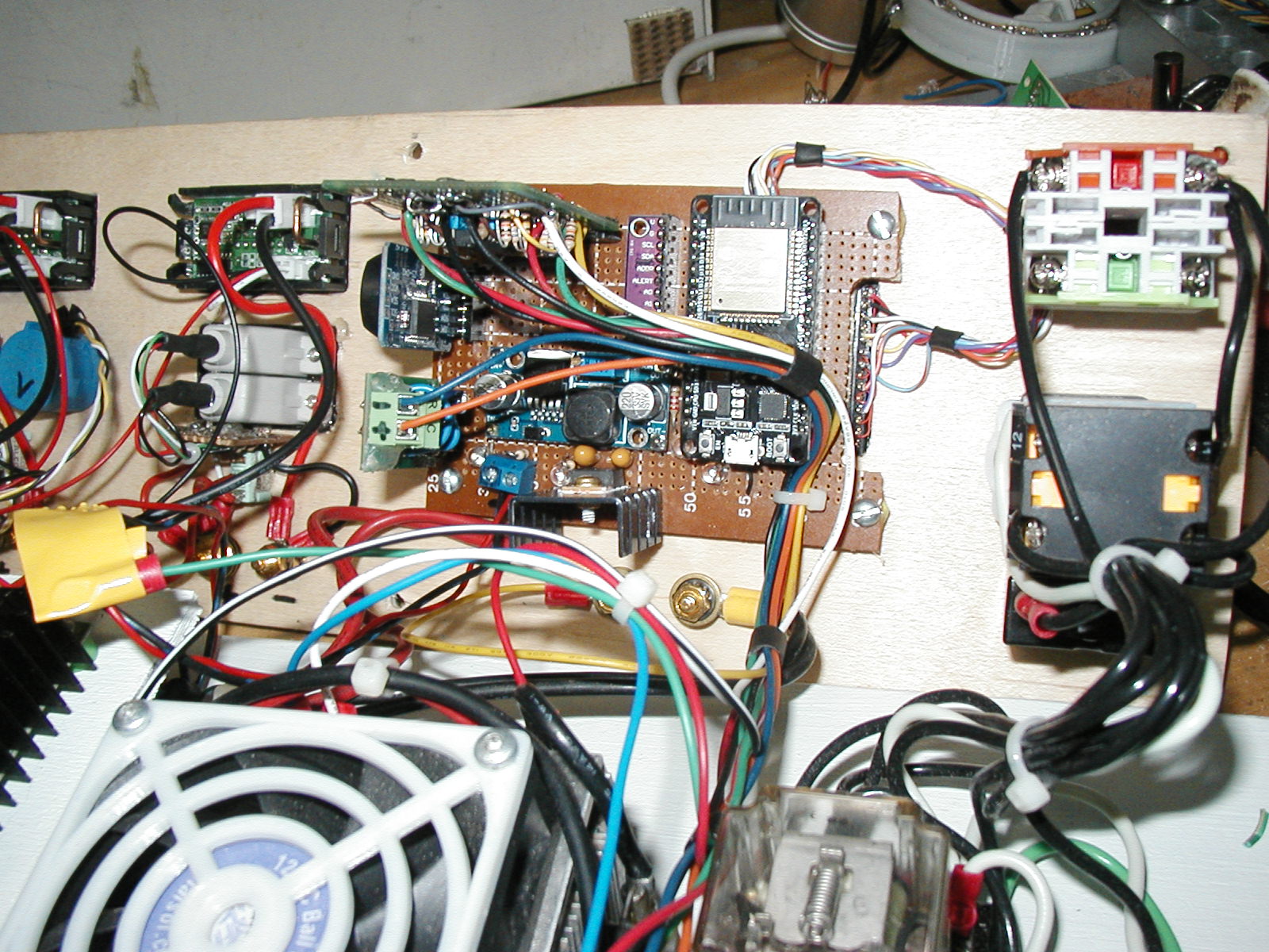
DC Load Control Board and Load Heatsink
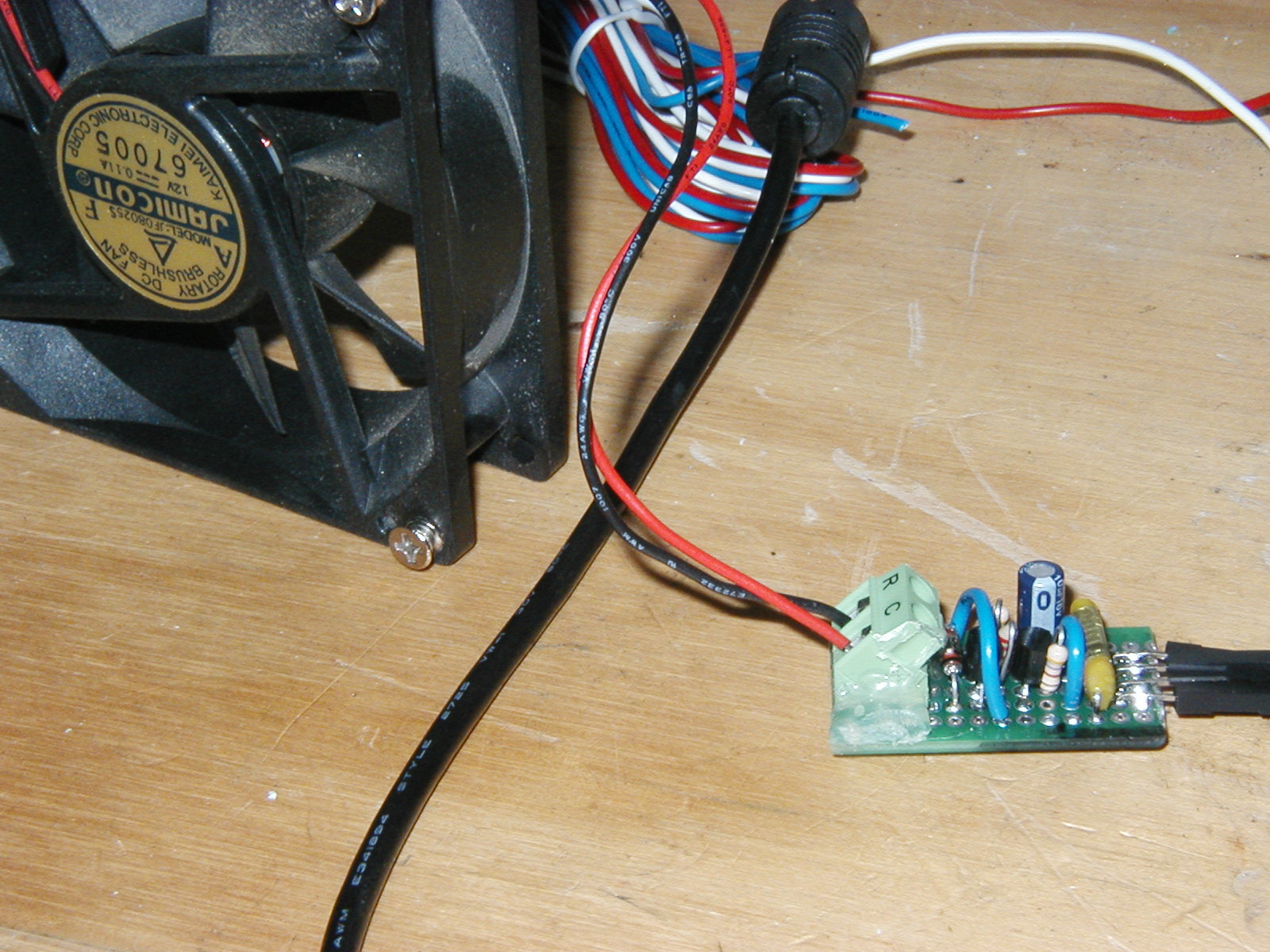
DC Load Control PWM Fan Control Board
When the load center is powered up, it displays a splash screen showing the owner and the software version.
There is a hidden touch sensitive area on the screen in the upper left corner.
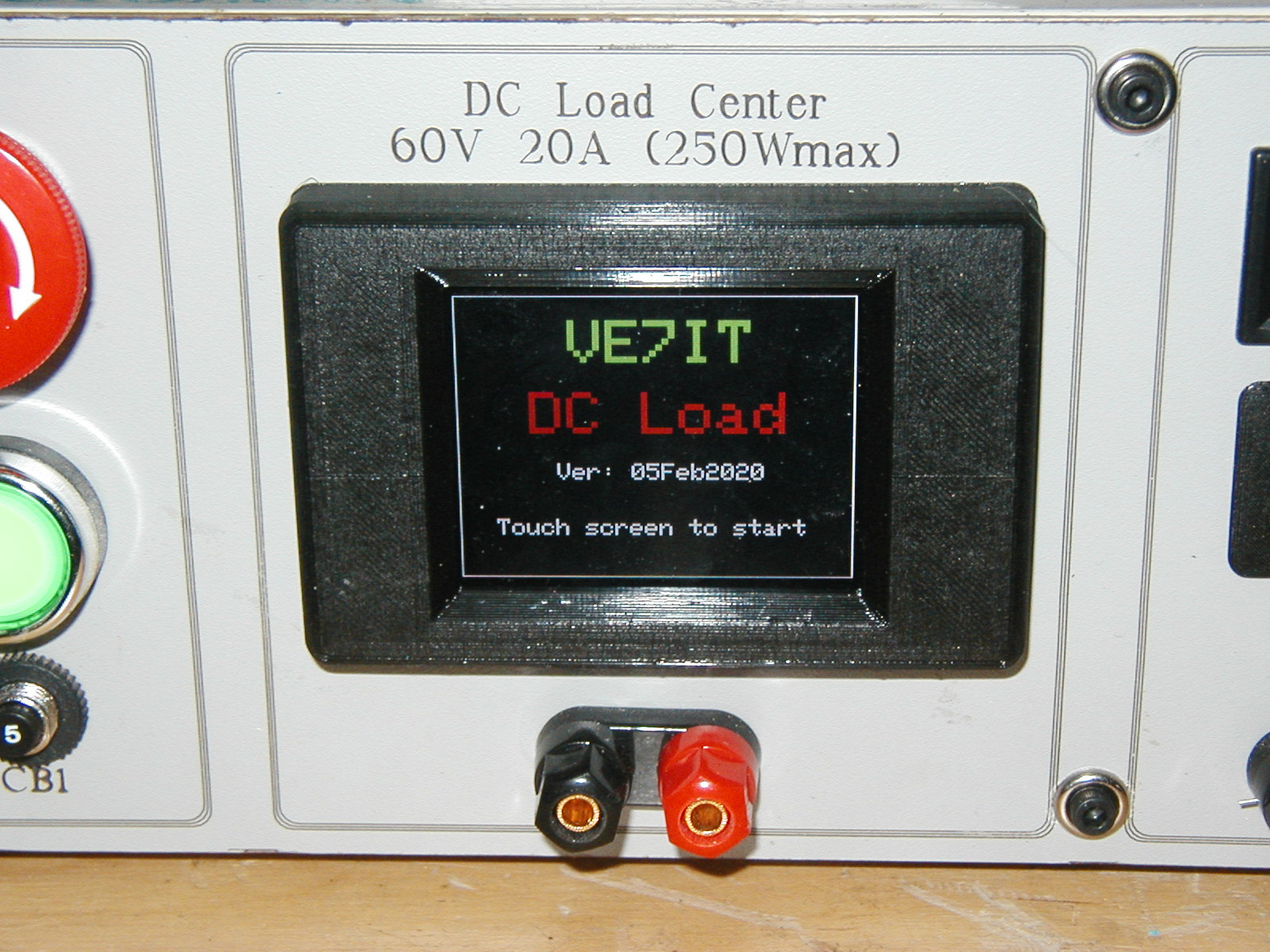
DC Load Splash Screen
If you press the screen right in the upper left corner, you will be presented with a diagnostics screen which is used to help calibrate the various analog sensors and the
PWM current setpoint output. The first 4 numbers are raw counts from the 16 bit A/D channels. The Temp number on channel 0
is showing that the 10K thermistor on the heatsink and the 10K pullup are giving us a reading of 13744 counts out of a possible 32767 or about 1/2 scale.
This indicates the thermistor connections are working and the heatsink is close to room temperature. The second channel of the A/D is labeled
Volts and is showing us that the voltage on the input is close to zero (4 counts out of 32767). By applying measured voltages to the input
connector and recording the Volts count, one can put the numbers into a spreadsheet and get a calibration equation for the voltmeter display
on the run screen. The I(1) and I(2) displays give us the raw A/D counts for the measuring circuit that is measuring the voltage across
the 0.1 ohm resistors on the fet load block. Applying a series of measured currents from an external power supply across each of the 0.1 ohm resistors
and recording the A/D counts will give us a calibration line for each channel of the current measuring system. The final display
"PWM" has a number that steps up every 5 seconds by 512 counts. By applying a power supply and ammeter to the load input terminals, the PWM current
command signal can be calibrated using the series of PWN counts output by the processor and the measured current draw. You will need a supply that
can supply close to 20A and a way to measure the current accurately to perform the calibration.
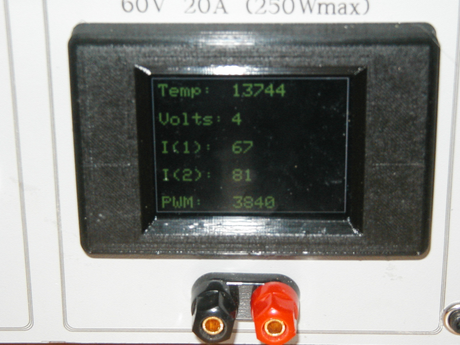
DC Load Calibration Screen
After the unit is powered up and displayed the splash screen, the default action is to drop into the clock display shown below.
The owner string and the heatsink temperature is displayed in the upper corners for reference.
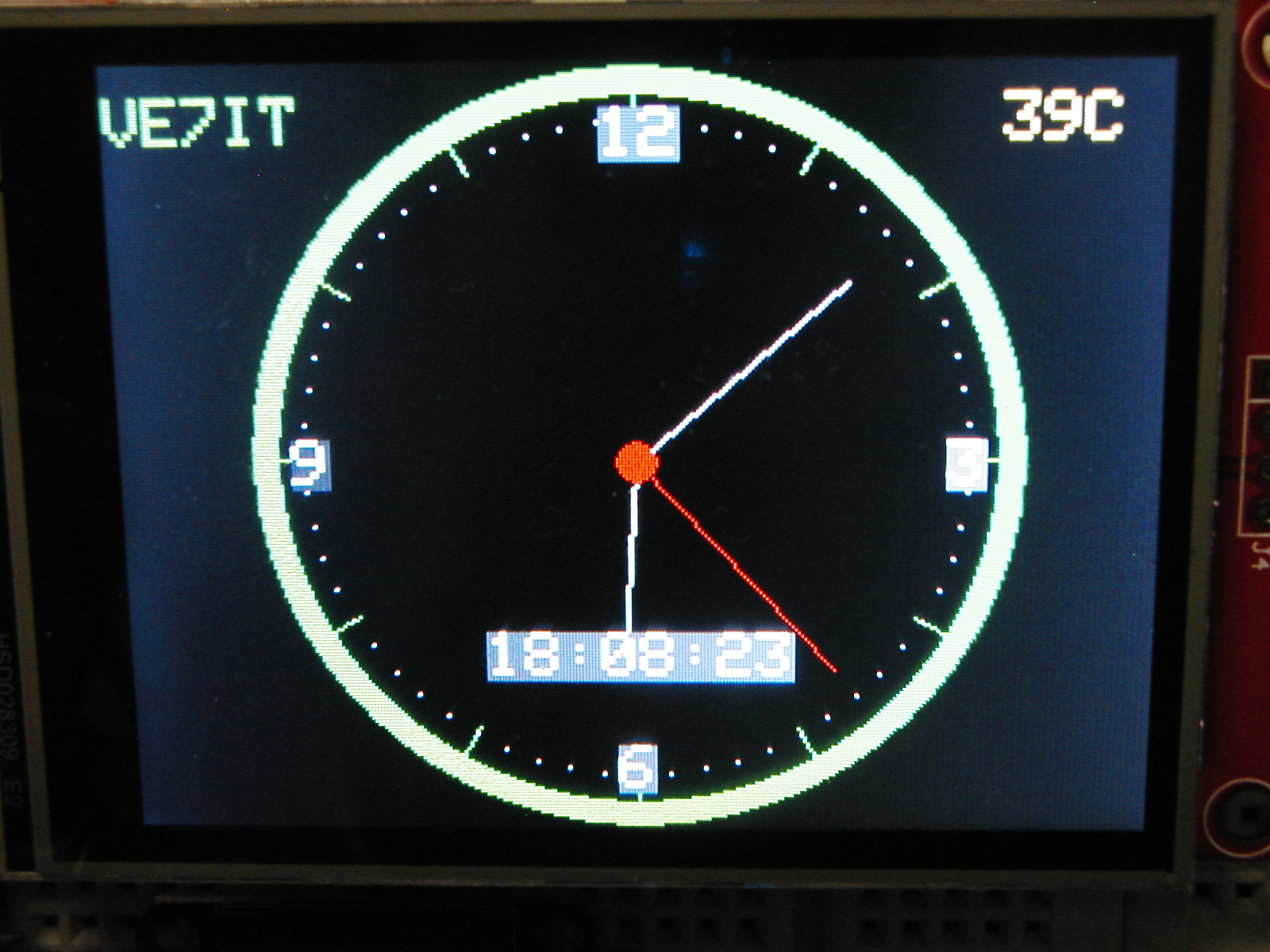
DC Load Clock (Idle display)
Touching the screen anywhere will switch you from the clock display to the setup screen.
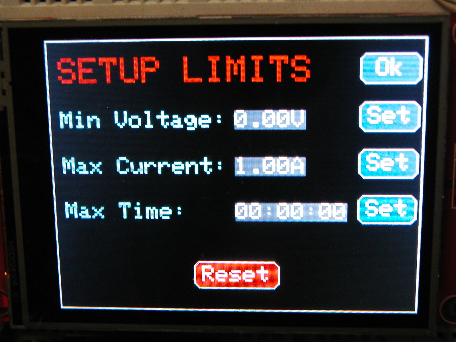
DC Load Setup Screen
There are several options that can be set on the setup screen. If you are testing batteries,
you probably want to terminate the load test when the battery voltage drops to some value. Enter this voltage
in the Min Voltage field by pressing on the set button next to the field. You will be presented with a numeric keypad to enter
the desired voltage. If you are just load testing a power supply, the voltage probably doesnt matter... you can leave it set at zero
and the voltage setting will not be used to terminate a test. The next setting is for programming the requested load current. This value defaults to 1A.
You can set the value from about 20ma to 20A by pressing the set button next to the field. The third setting is a time
in hours minutes and seconds. Setting this field will allow terminating the load test after a specified amount of time.
There is a secondary use of this field. If you want to set the RTC module time, enter the current time into the field and press the Reset
button on the bottom of the screen. To start a test, press the OK button. Pressing reset will take you back to the splash screen
(and after 30 seconds, the clock) and if the time field has an entry, will set the RTC module.
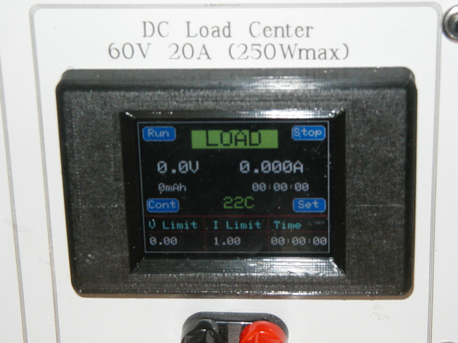
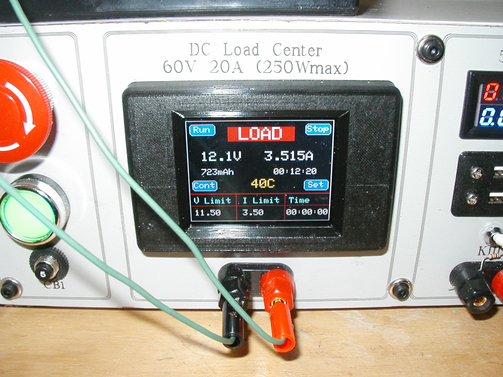
DC Load Run Screen
The run screen is where most of the action happens. The "LOAD" label will have a green background when the testing is idle and a red
background when there is an active test running.
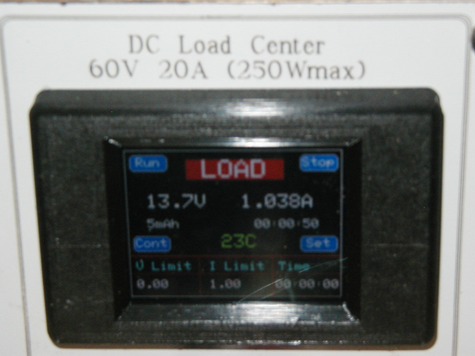
DC Load Run Screen
The two large numbers are the measured voltage on the load terminals and the measured current (combination of
both load fets). There will be a slight descrepancy between the measured current and the requested current limit as
there is no control loop active that makes them the same. They should be close if the installation calibrations were
done accurately. The smaller numbers on the next line down indicate the accumulation of mAh and the elapsed time for the test.
These are updated every second from the measured current and time from the RTC. The mAh display is typically used when
testing batteries and can be compared to the battery ratings. The next line has the measured heatsink temperature.
It will change from green to yellow at around 33C and to red at about 55C.
The fan on the DC load heatsink has its speed controlled
by this measured temperature. It will ramp up in speed as the temperature increases. If the heatsink
gets to 75C, any test in progress will be terminated. If the heatsink hits 65C, the current sink will be
turned off until the heatsink drops to 55C. This pulse mode of operation allows higher current testing
without cooking the FETs on the heatsink. When the fan starts at 33C it runs full speed for about 1/2 second
and then drops back to a slow speed. This is normal operation and is used to kick start the fan at slow speeds.
For reference, the test limits programmed in the setup screen are shown on the bottom line.
There are 4 buttons active on the run screen. The run button starts the test and resets the mAh and elapsed time accumulators.
The stop button will stop a test. The Cont(inue) button will continue a test that was interrupted. The set button
will suspend a test and get you back to the setup screen in case you want to adjust the one of the test limits.
To get back to the splash screen and eventually the clock, push the set button, then the reset button.
DC Power Supplies
The power supply section consists of three independant power supplies.
One of the three supplies is fixed at 5V and is used
for USB charging ports and a general 5V metered supply on the binding posts. The 5V metering makes it very easy
to see how much current the USB device is using to charge. Bad charging cables are very common
and the metered display makes it very obvious if you are trying to charge a device with a bad cable.
To make all the power supplies floating,
three separate AC powered 24VDC supplies are used to feed three adjustable power modules.
The output of these modules is then fed to LED digital meters to monitor voltage and current ouput.
Switches are used so that the output on the binding posts could be toggled on and off easily when
connecting or altering the supply settings. The 2 variable supplies have the voltage and current pots on the power
supply modules remoted to the front panel using 5K 10 turn pots.
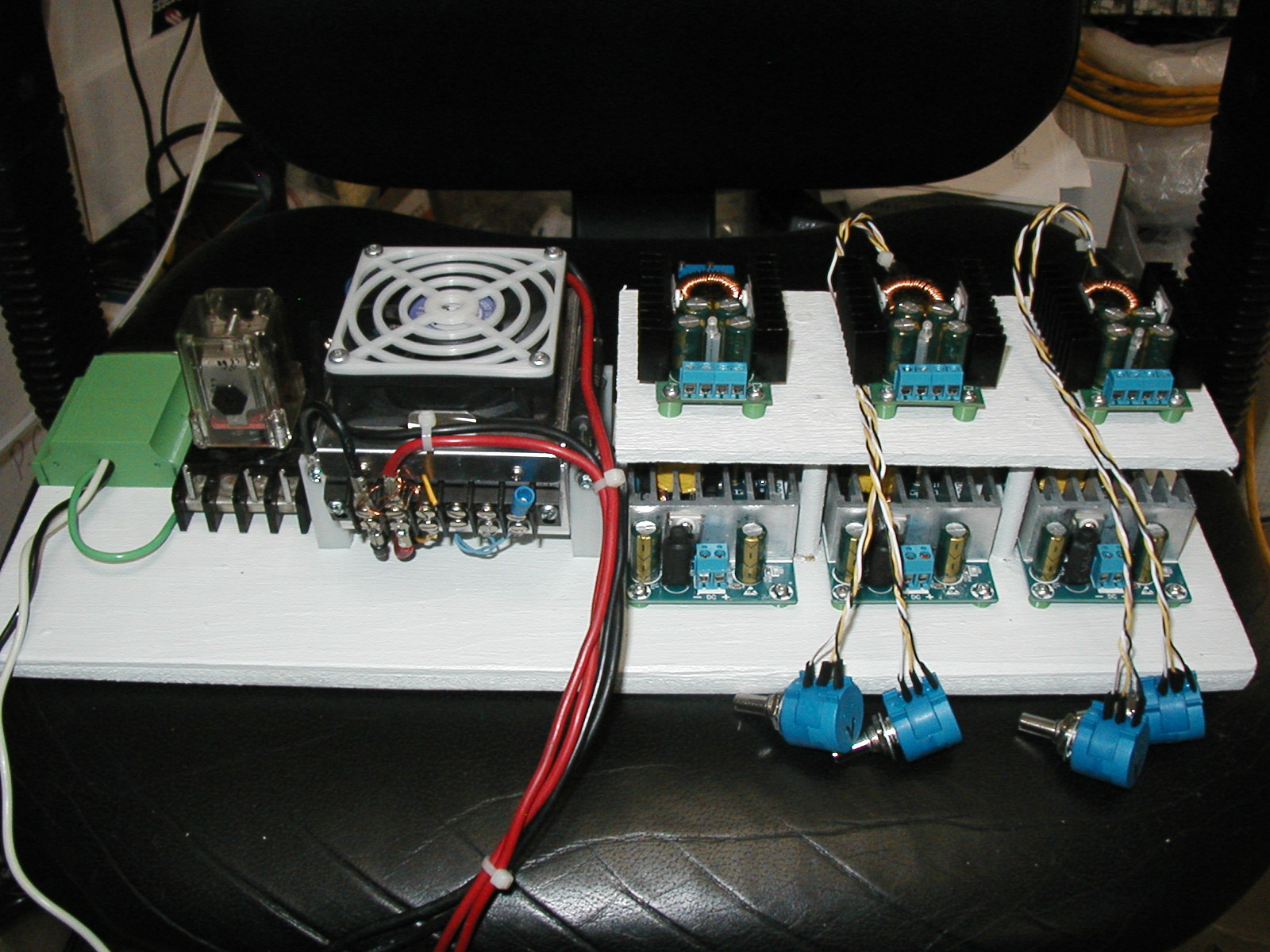
DC Power Modules
As seen in the picture above, the three 24VDC A/C powered supplies are on the bottom right with the
three DC voltage regulators on an elevated shelf above. The ten turn pots for the two variable supplies
are visable in the forground. The picture above shows the plywood sub chassis with most of the modules
in an unwired state.
The USB charging ports use the circuit below. This allows Samsung devices to detect the ports as high
current charging points.
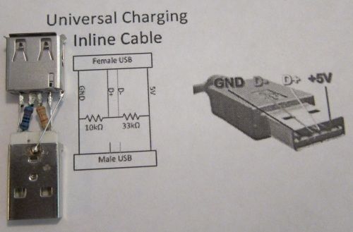
Samsung High Current Charging Connections
The above circuit is incorporated in the wiring of the 2 USB charging jacks and lets Samsung devices charge
at 1.5A instead of the USB default of 0.5A
The front panel is a piece of laser engraved arborite glued to some 3mm baltic birch plywood. This gives a very durable and nice looking panel.
Project Files
Schematic Drawing dc_load - dc_load.pdf(115K)
Schematic Drawing dc_panel - dc_panel.pdf(42K)
Kicad Project dc_load - Kicad_dc_load(356K)
Kicad Project dc_panel - Kicad_dc_panel(1.2Mb)
ESP-32 software dc_load - esp32-dcload.ino(45K)
VCarve Pro Project for laser engraving and cutouts - dc_panel.crv(1.7M)
3D Printed Bezel for Display - https://www.thingiverse.com/thing:4127586
 Back to my Project(s) Page